
Field Strength Meter

The wide band signal strength meter circuit is specifically engineered to operate within the VHF frequency range of 80 to 110 MHz, making it suitable for detecting both amplitude modulation (AM) and frequency modulation (FM) signals, as well as continuous wave (CW) transmissions. The fundamental operation of this circuit involves the conversion of RF signals into a direct current (DC) output, which is then amplified for easier measurement and display.
The circuit typically consists of an RF input stage, where the incoming RF signal is coupled through a matching network to optimize power transfer and minimize signal loss. The inductor L1 plays a crucial role in this stage, with specifications of 4 to 6 turns of 20 SWG (standard wire gauge) wire wound air-spaced on a quarter-inch former. This configuration allows for effective inductance and tuning, facilitating resonance at the target frequencies.
Following the input stage, the RF signal is rectified using a diode or a combination of diodes configured in a suitable arrangement to convert the AC signal into a pulsating DC signal. The rectified output is then filtered using capacitors to smooth the signal, ensuring that variations in RF energy are accurately represented as a stable DC level.
An operational amplifier or a transistor amplifier stage is employed to further amplify the filtered DC signal. This amplification is critical for enhancing the sensitivity of the meter, allowing it to detect even minor fluctuations in RF energy levels. The output from this amplification stage can be connected to a voltmeter or an analog meter display, providing a visual representation of the field strength.
Calibration of the circuit is essential to ensure accurate readings. This can be achieved by comparing the output voltage against known RF signal strengths and adjusting the gain of the amplifier stage accordingly. Additionally, the circuit may include a variable resistor or potentiometer to fine-tune the sensitivity and response characteristics.
In summary, this wide band signal strength meter circuit is a vital tool for RF signal analysis in the VHF spectrum, offering a reliable means of measuring field strength through a well-designed combination of inductive, rectification, and amplification components.This is a wide band signal strength meter circuit which responds to small changes in RF energy, designed to be used for the VHF spectrum and will respond to AM or FM modulation or just a plain carrier wave. This circuit measures radio field strength by converting the signal to DC and amplifying it. This field strength meter was designed for VHF frequencies in the range 80 -110 MHz.The inductor L1 is 4 to 6 turns of 20swg wire air spaced wound on a quarter inch former or similar.
🔗 External reference
Related Circuits
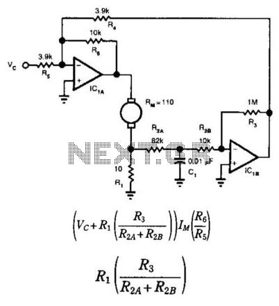
This circuit provides bidirectional speed regulation for small motors and does not require a tachometer. The voltage applied to the motor's windings, which is determined by summing amplifier IC1A, is expressed as a function of the command voltage (Vc)...
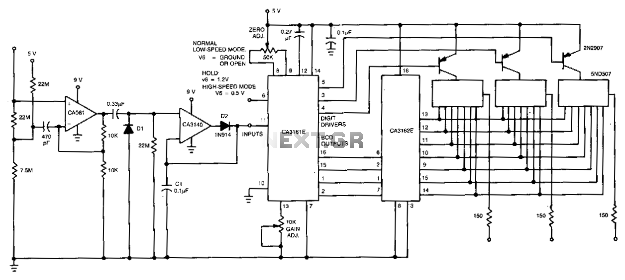
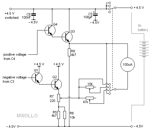
The CA081 and CA3140 BiMOS operational amplifiers provide minimal loading on the circuits being measured. The wide bandwidth and high slew rate of the CA081 enable the meter to function effectively at frequencies up to 0.5 MHz. The CA081 and...
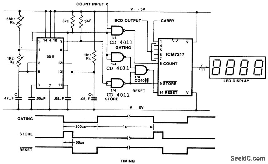
This is an inexpensive frequency counter and tachometer circuit. It utilizes a 556 dual timer to generate the gating, not-store, and not-reset signals for an ICM7217 counter. One timer operates as an astable multivibrator using resistors RA, RB, and...
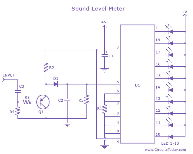
A sound level meter circuit with a diagram and schematic using the IC LM3915, which is an audio level measurement chip. It is used to display the sound level of an amplifier or a microphone. The sound level meter circuit...
This project, based on an article published in the February 2008 edition of Radcom (the magazine of the Radio Society of Great Britain), describes a meter with a 50-ohm input impedance designed for measuring very small RF powers. Many...
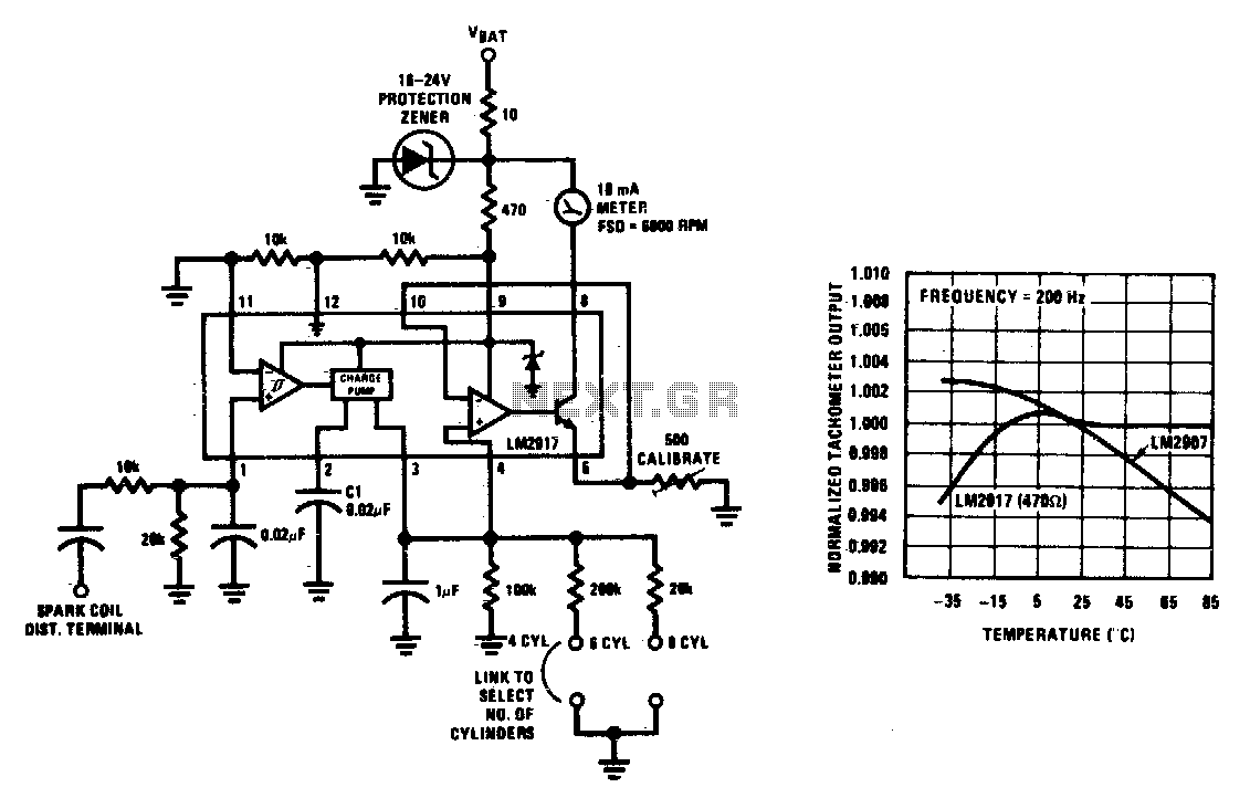
This tachometer can be configured for any number of cylinders by connecting the appropriate timing resistor as illustrated. A 500-ohm trim resistor can be utilized for final calibration. Additionally, a protection circuit consisting of a 10-ohm resistor and a...