
Gasoline engine tachometer

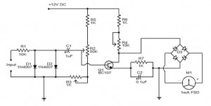
The tachometer circuit is designed to accurately measure the rotational speed of an engine, providing critical information for performance monitoring and diagnostics. The configuration allows for flexibility in the number of engine cylinders, which is essential for compatibility with various vehicle types. By selecting the correct timing resistor, the tachometer can be tailored to the specific engine configuration, ensuring precise readings.
The inclusion of a 500-ohm trim resistor serves as a calibration tool, allowing for fine-tuning of the output signal. This adjustment is crucial for achieving accurate RPM readings, as variations in engine characteristics can affect the tachometer's performance. The calibration process typically involves adjusting the trim resistor while monitoring the output to match the expected RPM values.
Furthermore, the protection circuit enhances the reliability of the tachometer by safeguarding it against electrical transients. The 10-ohm resistor limits the current flowing through the circuit, while the Zener diode provides a voltage clamping mechanism. This combination protects sensitive components from voltage spikes that can occur in automotive environments, thereby extending the lifespan and functionality of the tachometer.
Overall, this tachometer design integrates flexibility, precision calibration, and robust protection features, making it suitable for various automotive applications.This tachometer can be set up for any number of cylinders by linking the appropriate timing resistor as illustrated. A 500 ohm trim resistor can be used to set up final calibration A protection circuit composed of a 10 ohm resistor and a zener diode is also shown as a safety precaution against the transients which are to be found in automobiles.
Related Circuits
Wilf Rigter simplified this circuit a bit, made it phototropic, and doubled it up to yield a photopopper design in a post later the same day. I’ve got this design written up elsewhere in the library. The circuit described is...
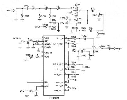
The objective of this project is to develop a multi-effect guitar processor capable of altering the tonal characteristics of a guitar. This device aims to provide a wide range of unique sounds, enhancing the entertainment value for users. The...
The electronic tachometer frequency converter circuit operates by converting the input signal into a proportional current that can be measured by a pointer device. The electronic tachometer frequency converter circuit is designed to accurately measure the rotational speed of a...
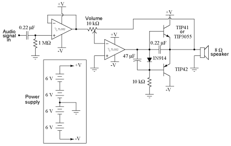
It is advisable to obtain TIP41 and TIP42 transistors, which are closely matched NPN and PNP power transistors with dissipation ratings of 65 watts each. If a TIP41 NPN transistor is unavailable, the TIP3055 (available from Radio Shack) serves...
This digital DIY tachometer for bicycles utilizes two reed switches to gather speed information. The reed switches are positioned near the wheel rim, where permanent magnets are mounted on the wheel spokes. As the spokes rotate, the magnets pass...

Approximately one month ago, an attempt was made to reverse engineer a low-cost LED color-changing light bulb. With assistance, the circuit has been mapped out, and control over the bulb has been established. However, several aspects of this device...