
Field Strength Meter

The Field Strength Meter circuit is designed to measure the strength of radio frequency (RF) signals in a given area. This type of circuit is particularly valuable for radio frequency hobbyists and enthusiasts who require a practical tool for evaluating signal strength during the development and testing of RF devices.
The circuit typically consists of a few essential components, including a diode, an operational amplifier (op-amp), a microcontroller, and a display unit. The diode is used to rectify the RF signal, converting it into a direct current (DC) voltage that can be processed. The op-amp amplifies this rectified signal, allowing for better sensitivity and accuracy in measurements.
A microcontroller may be implemented to digitize the amplified signal, facilitating the integration of additional features such as calibration, data logging, or signal processing. The output from the microcontroller can be displayed on an LCD or LED screen, providing a visual representation of the field strength.
Power supply requirements for the circuit can vary, but it is common to use a battery or a regulated power supply to ensure stable operation. Additionally, the circuit design may include input impedance matching components to optimize performance across a range of frequencies.
Overall, the Field Strength Meter circuit is a practical tool for anyone working with radio frequencies, enabling effective measurement and analysis of signal strengths in various applications.The following circuit shows about Field Strength Meter Circuit Diagram. Features: useful for radio frequency hobbyist and enthusiast, uses only .. 🔗 External reference
Related Circuits
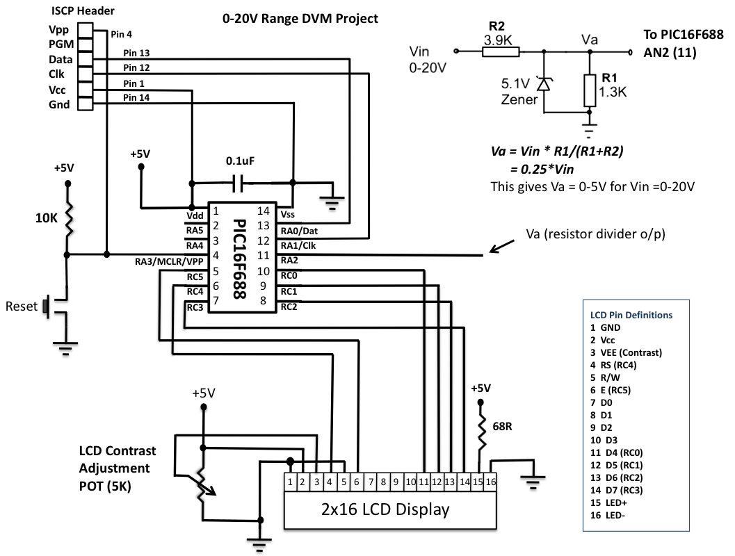
This is another version of an older digital voltmeter (DVM) project that was based on the PIC12F683 microcontroller. The previous version displayed the measured voltage on an LCD driven serially by the PIC12F683 using three I/O pins. The new...
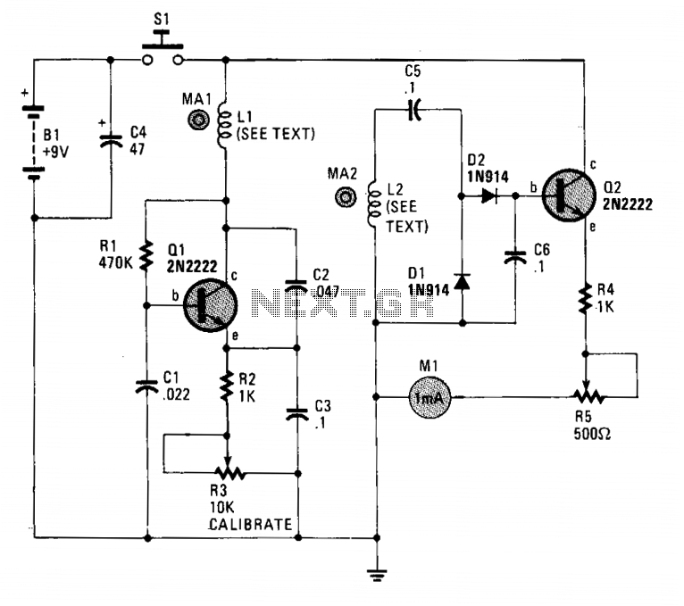
The circuit employs two general-purpose NPN transistors, Q1 and Q2, along with a specially designed hand-wound dual-coil probe to detect magnetic fields. Q1, along with its associated components, forms a simple Very Low Frequency (VLF) oscillator circuit, with L1,...
This circuit is designed for precise measurement of temperature in degrees Celsius. It features a transmitter section that converts the output voltage from the temperature sensor, which is proportional to the measured temperature, into a frequency signal. This frequency...
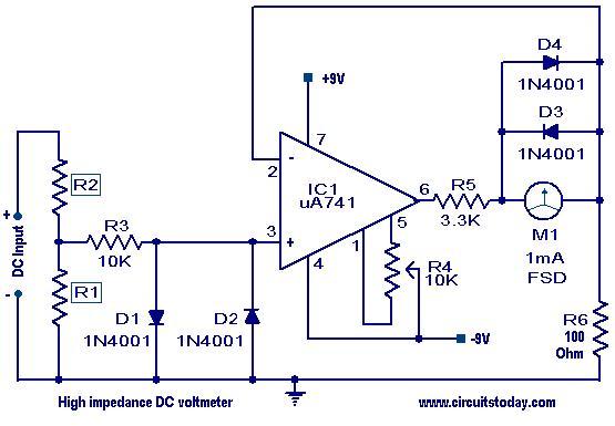
A high impedance DC voltmeter utilizing a uA741 integrated circuit (IC) is presented. The operational amplifier functions as a non-inverting DC amplifier, with negative feedback provided through a DC meter that requires 1mA for full-scale deflection. With R6 set...
This project was requested by several individuals who want to set up their home cinema systems by adjusting all loudspeaker outputs to the same level from the listening position. Essentially, this device functions as a straightforward (yet linear and...
.gif)
This circuit utilizes a single integrated circuit (IC) along with a minimal number of external components to display audio levels through ten LEDs. The input voltage range is from 12V to 20V, with a recommendation for 12V. The LM3915...