
Digital Remote Thermometer circuit

The circuit operates by utilizing a temperature sensor, such as a thermistor or an RTD (Resistance Temperature Detector), which generates a voltage that varies with temperature. This voltage is fed into a frequency-to-voltage converter circuit, which translates the analog voltage signal into a frequency output. This frequency output is then modulated and transmitted over the mains supply lines, leveraging existing electrical infrastructure for communication.
On the receiving end, a frequency counter is employed to detect the frequency bursts transmitted by the transmitter. The counter processes these bursts and converts them into a digital format suitable for display. The three 7-segment LED displays are configured to show the temperature reading in a clear and user-friendly manner, with the first two displays indicating whole degrees and the last display showing tenths of a degree.
Power supply considerations for both the transmitter and receiver are critical, as they must operate reliably over potentially long distances. The use of appropriate filtering and signal conditioning techniques is essential to minimize noise and interference from other devices connected to the mains supply. Additionally, the circuit can be designed to include features such as calibration adjustments to ensure accuracy and precision in temperature measurements.
Overall, this circuit provides a robust solution for remote temperature monitoring, suitable for various applications where wired connections are impractical or undesirable, while maintaining high accuracy and reliability in temperature measurement.This circuit is intended for precision centigrade temperature measurement, with a transmitter section converting to frequency the sensor`s output voltage, which is proportional to the measured temperature. The output frequency bursts are conveyed into the mains supply cables. The receiver section counts the bursts coming from mains supply and shows the counting on three 7-segment LED displays.
The least significant digit displays tenths of degree and then a 00.0 to 99.9 °C range is obtained. Transmitter-receiver distance can reach hundred meters, provided both units are connected to the mains supply within the control of the same light-meter.. 🔗 External reference
Related Circuits
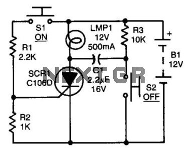
After the SCR is activated, capacitor CI charges up to nearly the full supply voltage through resistor R3 and the anode of the SCR. When switch S2 is later closed, it grounds the positive terminal of CI, causing the...
This electronic game pits a human player against the machine. The opponents use a common game token and take turns moving along a path by one, two, or three steps, with the winner being the first to reach the...
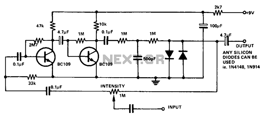
The circuit utilizes a transistor to amplify the input signal. Two diodes are employed to clamp the distorted output, while a 500 pF capacitor filters out high-frequency noise. Under normal conditions, a 1M slide rheostat is used to adjust...
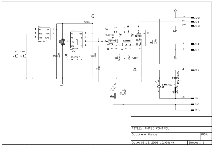
The following circuit illustrates a 2500W Phase Control Circuit Schematic. Features include a ground-tied trigger output that is disabled, and a low voltage input. The 2500W Phase Control Circuit is designed to regulate the power delivered to a load by...
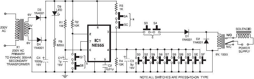
A simple electronic key code lock circuit that requires few external components can be constructed using this schematic diagram. This electronic key code lock circuit is based on a common 555 timer circuit and other standard components. This low-cost...
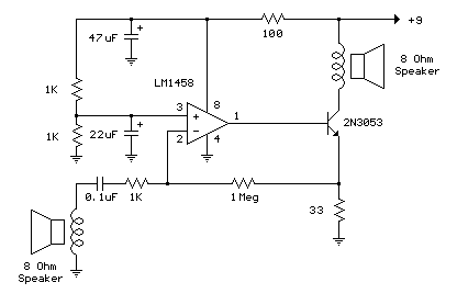
The example below illustrates using an op-amp as an audio amplifier for a simple intercom. A small 8 ohm speaker is used as a microphone which is coupled to the op-amp input through a 0.1uF capacitor. The speaker is...