
Finite State Machine Programmable Logic Controller

The project involves a compiler program written in Pascal, which serves as a tool for translating high-level programming code into machine-readable format. Compilers are essential in software development, as they facilitate the execution of programs written in languages like Pascal by converting them into executable code that can run on a computer's hardware.
The schematic for the compiler may include various components, such as a lexer (lexical analyzer), parser, semantic analyzer, and code generator. Each of these components has a specific function:
1. **Lexer**: This component reads the source code and breaks it down into tokens, which are the basic building blocks of the programming language syntax. The lexer eliminates whitespace and comments, focusing on keywords, identifiers, literals, and operators.
2. **Parser**: The parser takes the tokens produced by the lexer and arranges them into a parse tree or abstract syntax tree (AST). This structure represents the hierarchical syntax of the programming language, ensuring that the code adheres to the grammatical rules defined by the language specification.
3. **Semantic Analyzer**: After parsing, the semantic analyzer checks the AST for semantic correctness. This includes type checking, scope resolution, and ensuring that operations are valid according to the language's rules.
4. **Code Generator**: The final stage of the compilation process is the code generator, which translates the AST into machine code or intermediate code. This code is optimized for performance and can be executed by the target machine's processor.
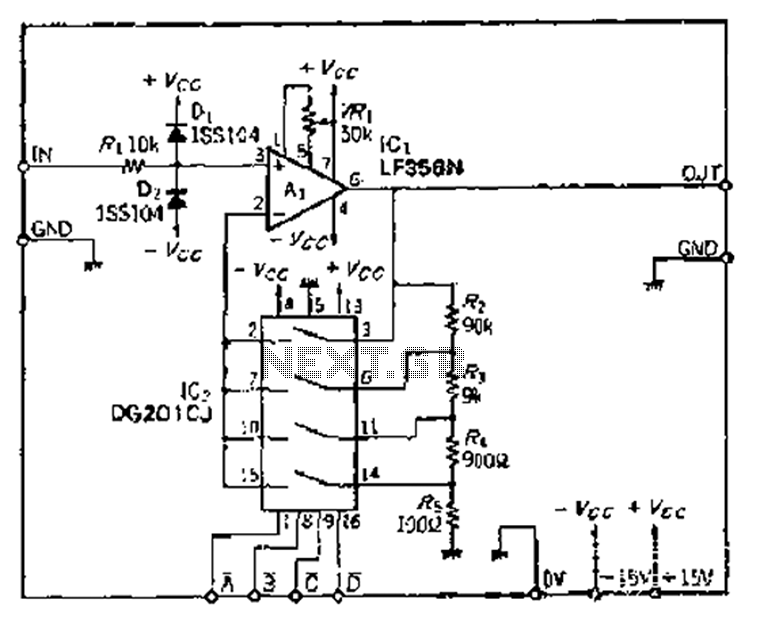
The architecture of the compiler can be represented in a flowchart or a block diagram, illustrating the input (source code), the various processing stages (lexer, parser, semantic analysis, code generation), and the output (executable code). Each component may also be represented in detail, including the algorithms used, data structures employed, and any specific optimizations implemented.
In summary, the Pascal compiler project encompasses a comprehensive system designed to transform high-level code into executable programs, with a structured approach that includes various essential components working in tandem to ensure accurate translation and execution.I have had this project hanging around for ages and have tried to submit it for publication without much enthusiasm so I will make everything available here for the individual constructor. The complete Pascal source code for the compiler program is available below. 🔗 External reference
Related Circuits
An exhaust fan is an essential component in kitchens. This circuit design aims to control kitchen fans by monitoring the ambient temperature. The described circuit utilizes a temperature sensor to detect the ambient temperature in the kitchen environment. When...
The Jiu zoom magnification circuit operates as an inverted feedback circuit, where the voltage division ratio is determined by a factor ranging from 2 to 5. This ratio establishes the partial pressure ratio, which can be selected through an...
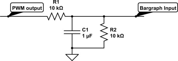
For a project, there is a need to display a progress bar representing the activity performed by a microcontroller unit (MCU). A bar graph display is intended for this purpose; however, the bar graph display driver IC, LM3914, requires...
The Dremel drill fitted with a mini drill-chuck on a stand is a great setup for drilling circuit boards. The problem is that it does not do low speeds very well. My unit had a failed internal speed controller,...
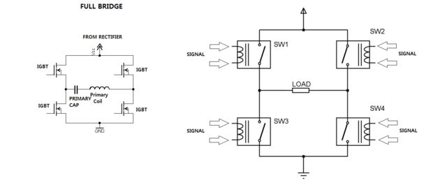
One of the most challenging aspects of constructing a solid-state Tesla coil is the bridge or switching circuit. The bridge switching circuit is the core component of the system. The bridge switching circuit is essential for controlling the power delivery...
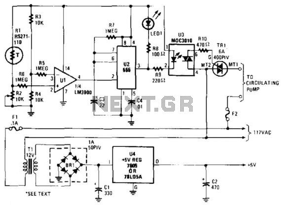
A thermistor (R1) is compared with a reference resistor (R2) in a Wheatstone bridge circuit. The output of comparator U1 goes high, which triggers U2. U2 introduces a delay of approximately 25 seconds. After 15 seconds, LED1 illuminates, U3...