
You can set 1 10 100 1000 times magnification programmable amplifier

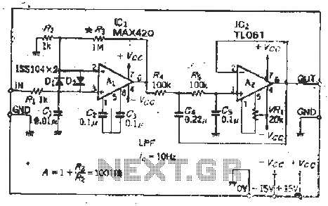
The Jiu zoom magnification circuit exemplifies a sophisticated design that leverages inverted feedback mechanisms to achieve variable gain based on external signal inputs. The voltage division ratio, set between 2 and 5, allows for flexibility in applications requiring different levels of magnification. The resistor divider configuration, specifically using a 90 kΩ and 10 kΩ resistor pair, is critical for establishing the desired partial pressure ratio. This ratio can be finely tuned by adjusting the resistor values, which directly influence the output characteristics of the circuit.
In high-precision applications, the selection of the resistor array is paramount, as it must ensure minimal deviation from the expected values. The inclusion of input protection components, such as diodes D- and Dz, enhances the circuit's reliability, safeguarding it against potential overvoltage conditions and ensuring stable operation during surgical procedures.
Moreover, the circuit's ability to modify the feedback division ratio is facilitated by the introduction of a small input bias current. This feature is particularly important for maintaining the integrity of the gain settings across various operational scenarios. The use of a FET input type operational amplifier is a strategic choice, as it provides high input impedance and low noise characteristics, essential for maintaining signal fidelity in variable gain applications. The requirement for offset adjustment underscores the need for precision in the overall circuit design, ensuring that the output remains consistent and accurate throughout its operational range.
Overall, the Jiu zoom magnification circuit presents a well-engineered solution for applications demanding variable gain and high precision, with robust design elements that enhance its functionality and reliability. Because the ball Jiu zoom magnification circuit is inverted feedback circuit voltage division ratio of the number of wells by the clamor of 2 to 5 to determine the partial pres sure ratio of the provision, the magnification selected by an external signal number. For example, If you need to d 10, in order to make partial pressure ratio of 1/10 can be used 90kQ: iokQ resistor divider circuit © in this order for each magnification to calculate the number of the circuit diagram parameters are derived. Since the resistor array selected with the adaptation resistor divider, so when the application objects requiring high precision, the circuit can be used Bong port input crown - and D-, Dz input protection circuit is used in the instrument during surgery circuit also without the crown, and D, Dz, in order to change the feedback circuit song dividing ratio to obtain variable gain, should be used before a small input bias current.
FET input type OP soul is in the mouth is a variable gain DC amplifier requires offset condensed whole circuit, the choice of the most
Related Circuits
I built this headphone amplifier for dynamic headphones based on my rules of proper audio design. People who know my designs will realize that this amplifier is much more than just a headphone amp. It is a pure class...

This is a 100 MHz Varicap Oscillator circuit. This circuit can provide modulation signals of less than 28 V and a frequency deviation of 28 MHz peak-to-peak. The 100 MHz Varicap Oscillator circuit is designed to generate high-frequency signals suitable...
Time would be better spent explaining transistor and MOSFET behavior in a simpler manner and focusing on digital circuitry and microcontroller projects. A transistor cannot simply be placed into a circuit and expected to yield calculated results. The gain...
This is a mini-sized power amplifier rated at 2 watts OTL that utilizes the LM380 integrated circuit. It serves as a ready-made circuit for audio applications and communication, requiring minimal external equipment. The capacitor C6 can be selected from...
The MAX420 is a monolithic chopper operational amplifier with a supply voltage of 15 V (ICL76s0 supply voltage of 15 V), exhibiting favorable input characteristics. The input offset voltage is 1 mV. Additional specifications include an input drift of...
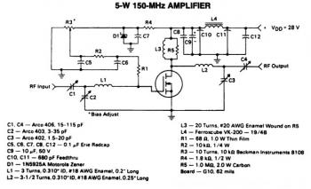
This is a 5W -150MHz RF amplifier circuit that utilizes the MRF123 TMOSFET. The MRF123 is a high-gain FET which may exhibit instability at both VHF and UHF frequencies; therefore, a 68 Ohm input loading resistor is employed to...