
Fire Alarm with LDR Sensor

The fire alarm circuit primarily consists of an LDR, which is a type of resistor that changes its resistance based on the intensity of light it receives. In the presence of smoke, which typically absorbs light, the resistance of the LDR increases, causing a change in voltage across the circuit. This voltage change can be monitored using a microcontroller or an operational amplifier, which can be configured to trigger an alarm when the smoke level exceeds a predefined threshold.
The circuit may include additional components such as a comparator to assess the voltage level from the LDR and a relay module to activate an external alarm or notification system. A power supply, usually a battery or a regulated DC source, is necessary to power the circuit.
For enhanced reliability, the circuit can be designed with a hysteresis feature to prevent false alarms due to transient changes in light levels. This can be achieved by incorporating feedback from the output of the comparator back to its input, ensuring that the alarm only activates under sustained conditions of smoke detection.
Furthermore, the integration of a buzzer or a LED indicator can provide immediate visual and auditory alerts to occupants in the vicinity, enhancing the safety measures in place. The design may also consider environmental factors, such as temperature and humidity, which can affect the performance of the LDR and overall circuit functionality.
In summary, this fire alarm circuit serves as a crucial safety device capable of detecting smoke through the use of an LDR, providing a timely warning to prevent fire-related accidents, particularly during high-risk seasons.This is the fire alarm circuit which use LDR to sense the smoke from the fire, so it can be used to detect any dark smoke. With the onset of summer season, possibilities of fire accidents go up. These fire accidents could be prevented if ti.. 🔗 External reference
Related Circuits

The power switch with an infrared proximity sensor is designed to detect obstructions at distances ranging from a few millimeters to several centimeters. The power switch utilizing an infrared proximity sensor operates on the principle of emitting infrared light and...
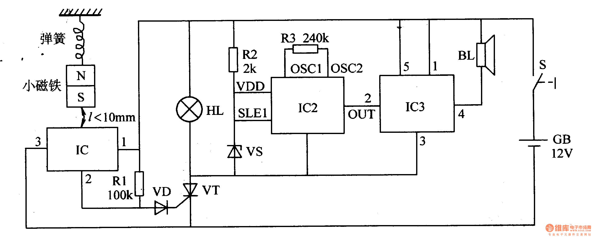
When the switch is activated, the seismic alarm enters a detection mode. In the absence of an earthquake, pin 3 of IC1 outputs a low signal, resulting in the disconnection of VT, which keeps the alarm circuit inactive. Upon...

When sufficient light reaches the Light Dependent Resistor (LDR) in this circuit, an alarm tone is activated on the loudspeaker. This tutorial guides beginners in electronics through the step-by-step process of constructing the circuit on a breadboard. The circuit utilizes...

This is a simplified schematic for the Solar Lifeforce. The design eliminates the expression/CV output features and the toggle for the buffer, making it a straightforward circuit. It may benefit from adding small capacitors between R5 and ground, as...

The ultra-simple tilt sensor alarm circuit can be constructed using readily available, inexpensive components. This circuit is based entirely on transistor technology. The homemade tilt sensor consists of a small glass or plastic bottle with two metal needles inserted...

The receiver circuit in Figure 1 activates an audio alarm when the transmitter (Figure 2) moves beyond a specified perimeter. The transmitter functions as a voltage-controlled oscillator, operating at approximately 915 MHz within the unlicensed ISM (industrial/scientific/medical) band. It...