
light activated alarm

The circuit utilizes a Light Dependent Resistor (LDR) as a light sensor, which changes its resistance based on the intensity of light falling on it. In bright conditions, the resistance of the LDR decreases, allowing more current to flow through the circuit. This change in current is detected by a microcontroller or a comparator circuit, which then triggers a sound-producing element, typically a buzzer or a loudspeaker, to emit an alarm tone.
The circuit is powered by a suitable voltage source, typically a battery or a DC power supply. The LDR is connected in a voltage divider configuration with a fixed resistor, which creates a variable voltage output that is fed into the input of the microcontroller or comparator. The output from this component controls the activation of the sound-producing device.
To construct the circuit on a breadboard, the following steps are recommended:
1. Place the LDR and the fixed resistor in series on the breadboard.
2. Connect the junction of the LDR and the resistor to the analog input pin of the microcontroller or comparator.
3. Connect the sound-producing device to a digital output pin of the microcontroller or comparator.
4. Ensure proper power connections to the microcontroller and the sound-producing device.
5. Program the microcontroller to monitor the voltage from the LDR and activate the alarm tone when the light intensity exceeds a predetermined threshold.
This project serves as an excellent introduction to basic electronic components, circuit design, and programming for beginners in electronics.When enough light falls on the LDR in this circuit, an alarm tone is played on the loudspeaker. This tutorial shows beginners in electronics how to build the circuit on breadboard step by step.. 🔗 External reference
Related Circuits
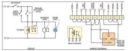
This low-cost burglar alarm utilizes a 12V strobe light and a truck reversing horn as the visible and audible outputs, respectively, while the alarm system operates on a 12V power supply. The burglar alarm circuit is designed to provide an...
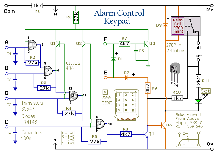
Pressing a single key on the keypad energizes the relay. Entering a four-digit code of your choice de-energizes the relay. This circuit is designed to control a Modular Burglar Alarm System but can be applied in other scenarios. A...

The 741 operational amplifier is configured as an audio oscillator using Radio Shack 276-677 photocells in the feedback circuits. When light strikes photocell PC1, its resistance decreases, resulting in a corresponding decrease in the frequency of the audio tone...
The T-40-16 and 555 ultrasonic transmitter circuit configuration consists of an ultrasonic transmitter T-40-16 and a 555 timer circuit. By adjusting the potentiometer RP, the oscillation frequency of the circuit can be changed. The output pulse frequency from the...
With RFT illuminated, point R goes to 0 volt and LM runs. With LFT illuminated, point R goes to 0 volt and RM runs. With RFT and/or LFT not illuminated, points R/L go to +9 volt; P1 and P2...

The Spartan-3 board features a traffic light controller utilizing FPGA I/O pins. The traffic light controller card consists of 12 point LEDs arranged in 4 lanes. Each lane is equipped with three LEDs: Go (Green), Listen (Yellow), and Stop...