
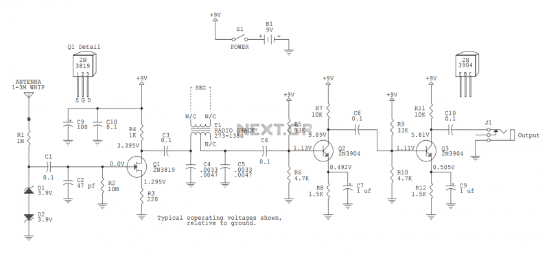
First Response Input Monitor Game Circuit

The First Response Monitor circuit is designed to facilitate real-time monitoring and selection of input signals in gaming and response applications. It typically consists of an input selector that routes signals from multiple sources to a single output, allowing for efficient management of data inputs from different game components or sensors.
The circuit can include a microcontroller or a dedicated input multiplexer, which serves as the core component for selecting the active input. The input selector can be configured to switch between various input sources, such as buttons, sensors, or other electronic devices, enabling the system to respond dynamically based on user interaction or environmental changes.
Signal conditioning elements may also be incorporated to ensure that the input signals are correctly formatted and amplified for processing. This might involve the use of operational amplifiers to enhance signal integrity or filters to eliminate noise.
The output of the circuit typically connects to a display or an output device, which visualizes the selected input or the monitored response. This can be particularly useful in gaming scenarios where quick feedback is essential for gameplay dynamics.
Overall, the First Response Monitor circuit is a versatile tool that enhances the interactivity and responsiveness of electronic systems, making it a valuable component in both gaming and monitoring applications.First Response Monitor, Input Selector, Game Circuit You can find first response using this circuit, because it helps many response monitor, games.. 🔗 External reference
Related Circuits
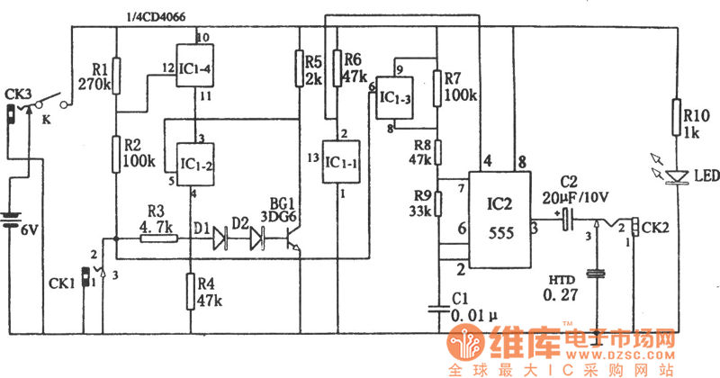
The circuit diagram illustrates a five-use tri-state audio logic pen utilizing components such as the CD4066 and a 555 timer. The primary elements include a multivibrator, a four-way switch (CD4066, designated as IC1), and a gate circuit formed by...
RF Wireless Data Transfer communication circuit diagram. A wireless communication interface was implemented to facilitate data transfer from one point to another using RF technology. The RF Wireless Data Transfer communication circuit utilizes radio frequency (RF) technology to establish a...

When light strikes the CDS cell, it activates the transistors, which in turn energizes the relay, causing it to latch. Pressing switch SI grounds the base of the 2N3565 transistor, thereby resetting the relay. Additionally, a 250 k potentiometer...
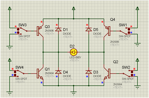
An H-bridge is a circuit configuration that enables the application of voltages in both directions. It permits higher voltage and current to be applied to the load while controlling the direction using a low voltage signal. The accompanying diagram...
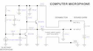
This microphone circuit was submitted by Lazar Pancic from Yugoslavia. The sound card for a PC typically features a microphone input, speaker output, and occasionally line inputs and outputs. The microphone input is designed specifically for dynamic microphones with...
This version sports a 2nd audio amplifier stage at Q3. The output level with this version is sufficient to drive a crystal headphone to a comfortable volume. The "crystal" headphone is like those used on ye olde crystal radios....