
Fish Tank Lights and Temperature Detector


1) Prep the Light Tube: Cut a section of the PVC conduit to the desired length using a hacksaw. Halve the pipe lengthwise and drill 16 evenly spaced holes in one half.
2) Mount and Wire LEDs: Secure an LED into each hole, alternating colors with hot glue. Once the glue has cured, wire the LEDs of the same color in series with appropriate current-limiting resistors.
3) Wire the Temperature Sensor: Connect the three-terminal temperature sensor to the appropriate cable. Use hot glue and heat shrink tubing to ensure a watertight seal. The temperature sensor used is the DS1822 model from Dallas Semiconductor.
4) Assemble the Light Tube: Connect the LED power wires to the cable and run the temperature sensor cable through the light tube, ensuring enough length protrudes for immersion in the water. Wrap the entire assembly in black electrical tape, ensuring the LEDs remain exposed.
5) Construct Circuit Board: Utilize perf board to create the circuit board, following the provided schematic to assist in the layout. Connect the board to a two-line LCD panel.
6) Connect External Cables to Control Unit: Power the unit with an 18V DC wall adapter. A 5V voltage regulator supplies stable power to the PIC microcontroller. Connect the temperature sensor and LED power cables to the perf board.
7) Wire up the LCD to the Control Unit: Refer to the schematic for pin-to-pin connections. This design is adapted from an older PIC microcontroller version, with unnecessary connections removed.
8) Mount Switch and LCD: Select a suitable project box to house the components. Drill and mount the switch on the case, ensuring the leads are long enough to connect to the perf board. Cut an opening for the LCD and secure it in place with hot glue.
9) Program the PIC: Download the microcontroller code and program the PIC using a suitable programmer.
10) Stuff Project Box: Securely place the perf board into the project box and close it using an appropriate method.
11) Entertain your Fish: Activate the system to display the colorful LED combinations, providing an engaging environment for the fish.
This project combines temperature monitoring and aesthetic lighting, enhancing both functionality and visual appeal in an aquarium setting.When the tank is cleaned the fish are removed and placed in a small amount of the tank water. The problem is that fish don’t like rapid temperature fluctuations. I guess a simple in tank or stick on thermometer would have done the trick but what is the fun in that? If the unit just did temperature monitoring it would have been such a waste of processor capability, so I thought adding colored lighting would be a great addition.
Uses 16 high power LED’s, 4 red, 4 green, 4 white and 4 blue. The tube that the LEDs are mounted in is a section of 3/4 inch PVC conduit. LCD Display to display the mode the unit is in and show the temperature. Liquid sealed temperature to read the water temperature. One button to change between modes. Photocell to turn off the lights when there is adequate room light. This is wired and calibrated but this function has been remove to allow the lights to remain on all the time. 1) Prep the Light Tube: Cut a section of the PVC Conduit to the desired length, a hacksaw makes quick work of this type of pipe. Cut the pipe in half length wise, drill 16 evenly spaced holes in one of the halves. 2) Mount and Wire LED’s: Hot glue an LED into each of the holes alternating the colors. After the glue is dry, wire up the like colored LED’s in series with an adequate current limiting resistor.
3) Wire the Temperature Sensor: Connect the 3 terminal temperature sensor up to the cable that will be used. Hot glue and heat shrink will make for a water tight seal. The temperature sensor being used is made by Dallas Semiconductor, it is model DS1822. 4) Assemble the Light Tube: Connect the LED power connections to the cable that will be used. Lay the temperature sensor cable through the light tube leaving enough sticking out the side to dip into the water from the height the unit will be mounted.
Wrap the entire light tube in black electrical tape, making sure the LED’s are not covered. 5) Construct Circuit Board: Use some perf board to create the circuit board, there is schematic below to aid in the construction of the circuit. Wire it up to a 2 line LCD panel. 6) Connect External Cables to Control Unit: To power this unit I used an 18VDC wall wart type power supply.
A 5V regulator was used to provide stable and clean power the PIC. Hook up the temperature sensor wires LED power cable to the perf board. 7) Wire up the LCD to the Control Unit: See the schematic below for the pin to pin connections. This was adapted from an old version of PIC microcontroller, all of the non 16f628 connections have been cleaned up. Mount Switch and LCD: Find an adequate project box to house the guts. Hopefully yours will look better than my old 5 ¼ floppy drive storage case. I was going to use a slick clear plastic project box and spray the inside black (after masking off the LCD area).
Well the spray paint I bought started to eat the plastic Drill and mount the switch on the case with leads long enough to tie into perf board. Cut a hole in the case and mount the LCD, hot glue is my friend in this case. 9) Program the PIC: Download the PIC microcontroller code and burn it onto the chip using a programmer.
10) Stuff Project Box: Jam the perf board into the project box and close it with something better than the tie strap that I am using 11) Entertain you Fish: Turn on the system and amaze your fish with the nice color combinations! 🔗 External reference
Related Circuits
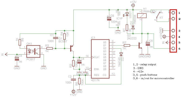
This circuit is operating the room illuminates. The basic component of the circuit is a IC1 (CD4017). Push buttons room are connected by normally wired to the circuit. All circuit is separately by optocoupler, which means that the circuit...
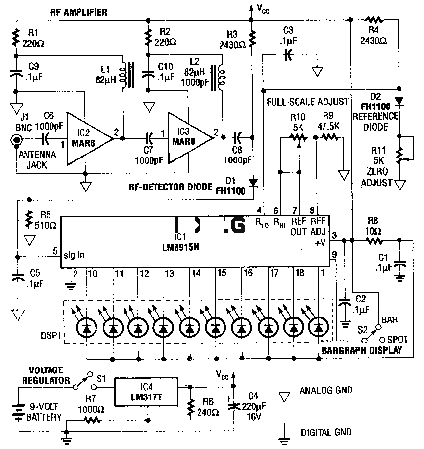
This RF detector is capable of locating low-power transmitters (such as bugs) that are not visible. It can detect the presence of a 1-mW transmitter from a distance of 20 feet, making it sensitive enough to identify even the...
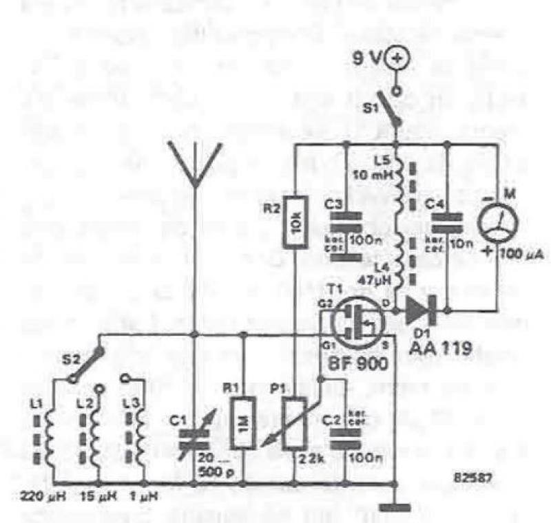
An RF field detector circuit suitable for measuring and verifying the power of antennas and transmitters can be constructed using transistors and common electronic components. This circuit employs a radio frequency transistor, specifically a MOS-FET with two gates. The...
This circuit controls a load, specifically a DC brushless fan, based on a temperature comparison with a setpoint. The transducer utilized is a diode in the forward bias configuration. When forward biased, the forward voltage drop across the diode...
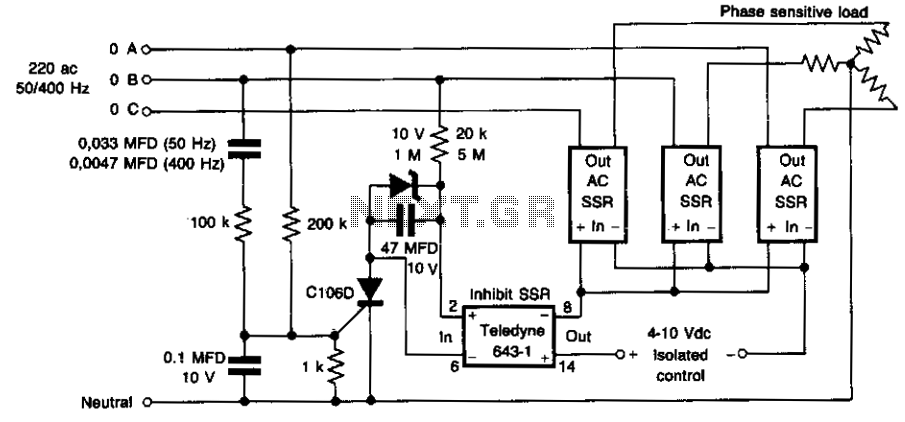
This circuit prevents damage to the load due to incorrect phasing. The three power solid-state relays (SSRs) are only permitted to turn on for a phase sequence where phase A leads phase B. If phase A lags phase B,...
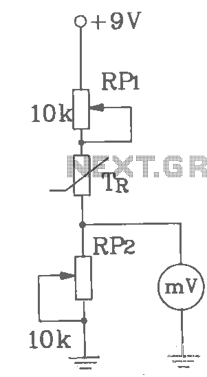
T-121 temperature sensor electronic thermometer circuit diagram shown below The T-121 temperature sensor circuit is designed to measure and display temperature readings accurately. The circuit typically consists of a temperature sensor, such as the T-121, which converts temperature variations into...