
Fitting Extension BT Sockets

To effectively extend BT telephone sockets while minimizing noise and crosstalk, it is crucial to adhere to proper cabling practices, particularly the use of twisted pairs. Twisted pair cables consist of pairs of wires twisted together, which helps to cancel out electromagnetic interference and maintain signal integrity.
In a typical installation, each telephone line should be run through its own twisted pair within the cable. For example, if two lines are required, one should utilize a four-pair cable, where each line is assigned its own pair. The pairs are typically color-coded for easy identification, with standard color codes being blue/white, orange/white, green/white, and brown/white.
When extending the telephone sockets, ensure that the connections are made at the junction points using proper connectors, such as RJ11 or RJ45, depending on the application. The wiring should be maintained in a manner that preserves the twists of the pairs as much as possible, especially within the termination points. This helps to reduce the potential for crosstalk and ensures that the telephone lines operate effectively without introducing hum or noise.
It is also advisable to keep the cable runs as short as feasible to further reduce the risk of interference. Additionally, avoid running telephone cables parallel to power lines or other sources of electromagnetic interference, as this can adversely affect the quality of the signal.
In summary, by following proper cabling techniques and ensuring the correct use of twisted pairs, the integrity of the telephone lines can be maintained, thereby preventing issues such as hum and crosstalk when extending BT telephone sockets.Extending BT telephone sockets can result in hum appearing on the line or, if two telephone lines are taken through the same cable, cross talk from one line to another. This is simply the lack of using twisted pairs correctly, here we show you how it should be done.. 🔗 External reference
Related Circuits
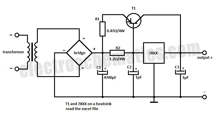
This voltage regulator extension circuit allows for an increase in output current up to 10 A. The T1 power transistor is configured with a resistor in the emitter. This voltage regulator extension circuit is designed to enhance the output current...
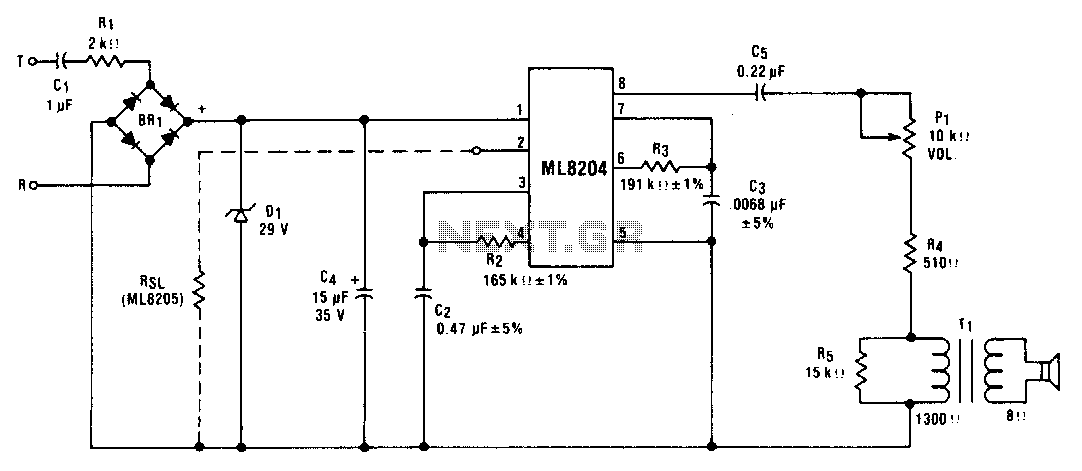
This circuit utilizes ML8204/ML8205 devices. The components illustrated result in an output frequency that oscillates between 512 Hz (fin) and 640 Hz (fb) at a modulation rate of 10 Hz (t). The circuit employing ML8204/ML8205 devices is designed for frequency...
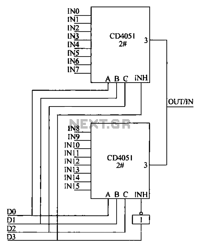
The CD4051 is a single-ended input 8-channel multiplexer that features three channel select inputs (A, B, C) and an inhibit input (INH). The signals at inputs A, B, and C are utilized to control the selection of one of...
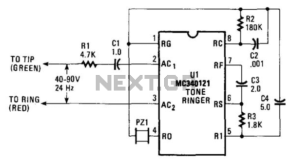
The AC ringing voltage, typically ranging from 40 to 90 V at 26 Hz, is rectified by U1, the tone-ringer integrated circuit (IC), which is utilized to drive the internal tone-generator circuitry. This tone-generator IC comprises a relaxation oscillator...
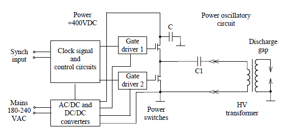
Simulate the electric field within a gas-filled discharge gap generated by a radio frequency voltage generator. The circuit, provided by the experimenters at a distance, is depicted in the accompanying image. The numerical values are as follows: C1 =...
Create a simple telephone-based intercom system in a new house. Shouting between rooms is not effective, and using an instant messaging client or FaceTime lacks the immediacy of a voice call. A collection of old wired telephones is available...