
Analog multiplexer CD4051 extension circuit 1

The CD4051 multiplexer is designed to facilitate the routing of multiple signals to a single output, making it highly useful in applications where signal management is critical. The device operates by allowing one of eight input signals to be selected and passed to the output based on the binary values present at the select inputs A, B, and C. The inhibit input (INH) provides additional control, allowing for the disabling of the selected channel when necessary.
In a multi-chip configuration, the proper management of the control signals is essential to ensure that only one multiplexer is active at any given time, thus preventing signal interference. This is achieved by using a combination of logic gates, such as inverters, to manage the enable states of each multiplexer. The design allows for scalability, enabling the user to expand the number of channels by simply adding more CD4051 devices and correctly configuring the address lines.
The integration of multiple CD4051 devices in a single system can be particularly advantageous in complex measurement and control applications, such as data acquisition systems, automated testing setups, and communication systems, where a large number of signals need to be multiplexed efficiently. The careful arrangement of the select lines and the inhibit input ensures that the system remains responsive and reliable, providing a robust solution for channel selection in electronic circuits. CD4051 is a single-ended input 8-channel multiplexer, it comes with three-pass channel select inputs A, B, C, and an inhibit input INH, input terminals A, B, C signal is used t o control the selection of eight channels It is turned on. In practice, if more than 8 measured parameters, using ten CD4051 multiplexer does not meet the requirements of large ones, which can be more than CD4051 connected and extended. Fig. 27-6 is composed of two CD4051 16 -channel multiplexer connection diagram. When multi-chip l switch-on work, multiplexer chip 2 on all off; on the contrary, the chip multiplex 2 opening when switched off, then the multi-switch chip 1 on all disconnected.
So, as long as a address (or data) line as the chip 1 and the chip 2 to allow control system side selection signal, and the two chip select input channels share a group address (or data) line. By changing the channel select lines D3 ~ DO status can gating one of the 16 channels INO ~ IN15. D3 is used to control the chip 1 and the core chip level INH input terminal 2. When D3-0 at which the chip l is fed in, in this context, DZ-DO terminal status is changed, only the strobe INO ~ IN7 one.
When D3-1 time, via the inverter goes low, the chip 2 is selected, this time, D2--; DO these three state lines, make the corresponding channel IN8-IN15 being turned on.
Related Circuits
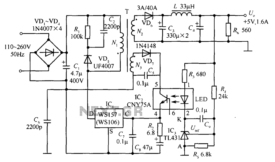
The circuit incorporates an optical coupler (CNY75A) and an adjustable precision shunt regulator (TL431). It includes current limiting resistors R3, R4, and R5 for the sampling resistor. As the output voltage (Uo) varies, the voltage across the sampling resistor...
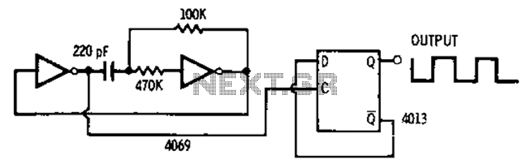
The 4013 pairs of D-type flip-flops in the astable multivibrator configuration are utilized as a binary divider output, generating an output frequency that is symmetrical, with a duty cycle of 50%. The 4013 integrated circuit contains two D-type flip-flops that...
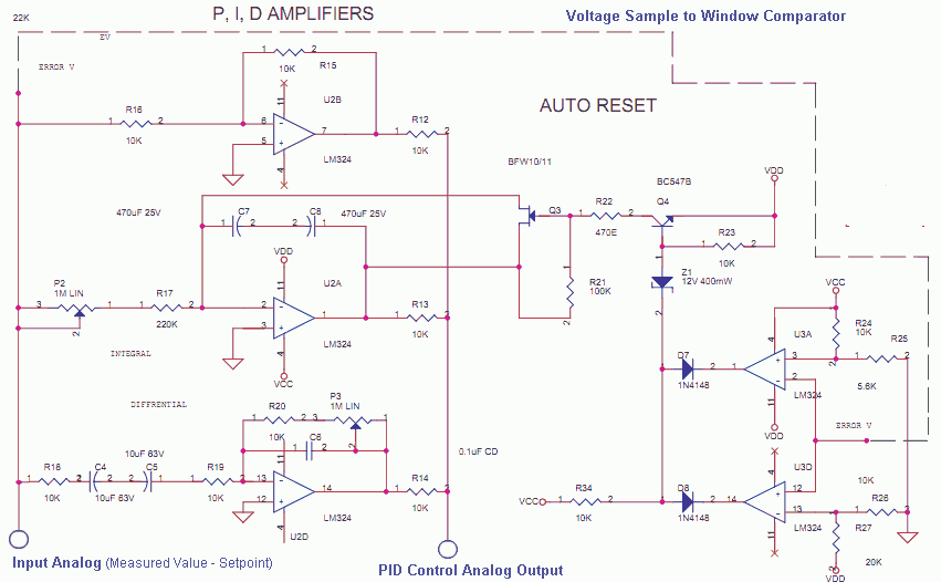
The Measured Value and the Setpoint are two inputs to a control system. The Measured Value is the amplified input from a transducer or sensor for a specific parameter that requires regulation, such as pressure or temperature. The Setpoint...
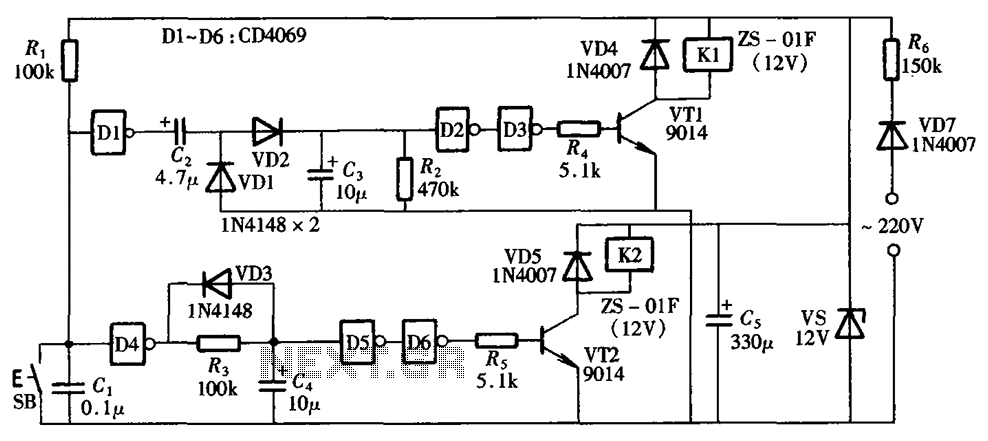
A one-button control switch is designed to control two relays, each of which can switch the load power on and off as needed. The circuit primarily consists of a hex inverter CD4049 and two self-locking DC relays. The circuit utilizes...
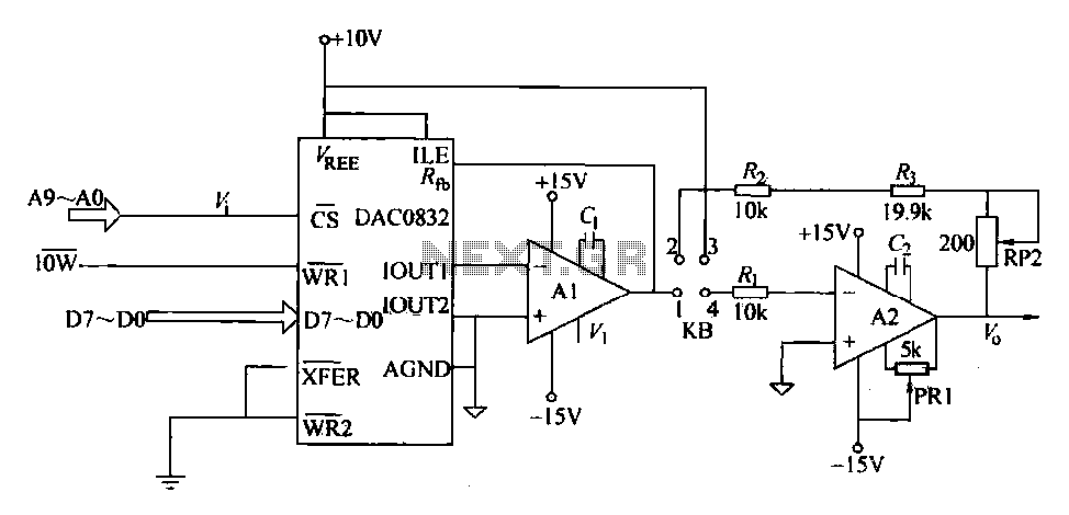
The DAC0832 is a digital-to-analog converter (DAC) chip designed for integration with computer bus systems. It features an 8-bit resolution and operates with a single power supply ranging from 5 to 15 volts. The device is compatible with TTL...
The closed-loop system consists of longitudinal and transverse components. The circuit operates as follows: a control circuit from the stepping motor CNC system issues a command, which the receiver detects. This signal is processed through a phase-sensitive rectifier to...