
Visible-Light Audio Transmitter Circuit

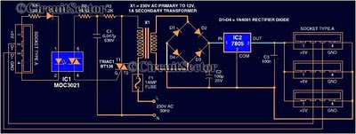
The visible-light transmitter circuit employs a 7805 voltage regulator, which is typically used to provide a stable output voltage of 5V. In this application, it is configured to operate in a variable-voltage mode. This configuration allows the output voltage to be modulated based on the input audio signal. The audio signal, which contains the information intended for transmission, is fed into the common input of the voltage regulator.
As the audio signal varies, it causes corresponding fluctuations in the output voltage of the 7805 regulator. These modulated voltage changes are then used to drive an incandescent lamp. The lamp acts as the transmission medium, emitting light that varies in intensity in accordance with the modulated voltage. This variation in light intensity encodes the audio information, allowing it to be transmitted over a distance.
This method of communication exploits the properties of visible light, making it suitable for applications where radio frequency transmission may be undesirable or impractical. The incandescent lamp's response to the modulated voltage ensures that the transmitted light is directly representative of the input audio signal, enabling effective communication through visible light. In the visible-light transmitter, a 7805 voltage regulator is connected in a variable-voltage configuration, and an audio signal is fed to the common input, to modulate the output voltage. The modulated output voltage is used to transmit intelligence via an incandescent lamp.
Related Circuits

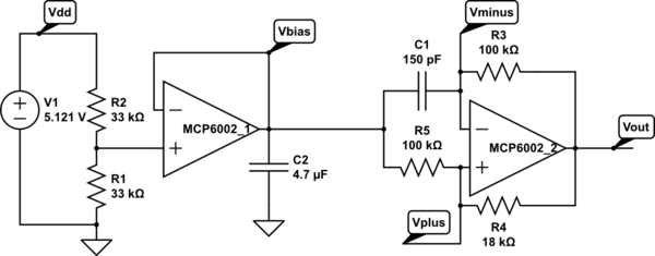
The three-channel amplifier output distribution uses a single TL084. The first step is to capacitive coupling with a 1.0 µF electrolytic capacitor. The entries are railways Vee Y2 or 4.5 V. This allows using a single 9 V power...
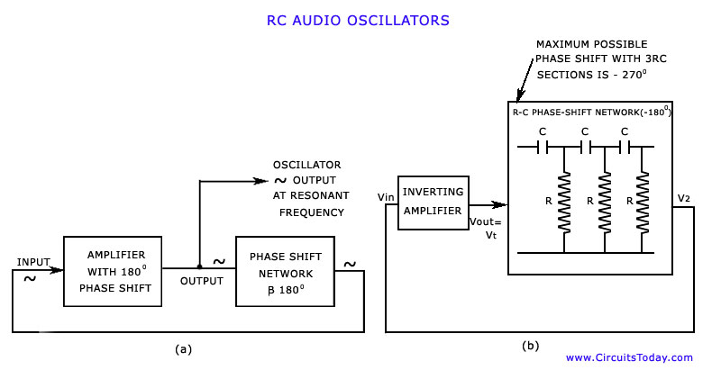
The discussion has focused on oscillators that utilize L-C tuned circuits, which create a 180° phase shift due to inductive or capacitive coupling, in addition to another 180° phase shift produced by the transistor itself. These L-C oscillators are...
Most peripherals that interface with a PC utilize a USB port. The computer's power supply circuit, specifically the switched-mode power supply (SMPS), is designed to provide constant power to all internal components. However, when external peripherals that require a...
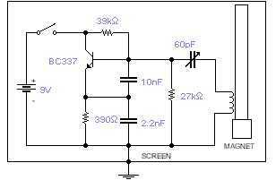
This basic oscillator will detect the Earth magnetic field. The ferrite rod and coil are taken from an old Medium Wave receiver and a small magnet is glued at one end. Tune to a medium wave commercial station until...
A touch sensor relaxation oscillator is utilized in the hysteresis lab. In this schematic, the variable capacitor is represented by a person's finger and a touch plate made from aluminum foil and packing tape. Code was developed for the...
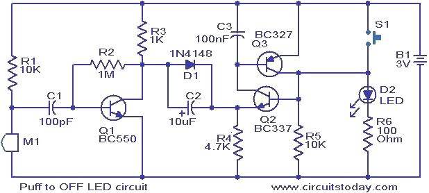
This circuit features an LED that can be turned off with a puff of air. A condenser microphone (M1) detects the puff. When the push button switch S1 is activated, transistors Q2 and Q3, configured as a latching pair,...