
Flash Slave Trigger

The flash slave circuit utilizes a phototransistor (Q1) to detect the initial flash from a master unit. Upon detection, the phototransistor activates a silicon-controlled rectifier (SCR1) that triggers additional flash units. The phototransistor is positioned to face the master flash to ensure reliable detection of the flash pulse. The sensitivity of the circuit is controlled by a variable resistor (R1), allowing for adjustments based on ambient lighting conditions or the intensity of the master flash.
When configuring the circuit, it is critical to set R1 to a level that maximizes sensitivity while avoiding false triggers from ambient light or other unintended sources. The SCR1 operates at high voltage levels, typically between 50V and 300V, making it essential to handle the circuit with caution to prevent electric shock.
The overall design of the flash slave circuit is straightforward, yet it provides significant flexibility for photographers looking to expand their lighting capabilities. By connecting multiple slave units, users can achieve a more dynamic lighting setup, enhancing the quality of their photography. Proper attention to component placement and adjustment will ensure optimal performance and safety during operation.Flash slaves are used when you need to supplement one flash unit with one or several more. This slave trigger simply triggers those other units. It does this by "seeing" the first flash (using a phototransistor) and triggering the other flashes a few microseconds later. The sensitivity of the circuit is adjustable to compensate for ambient light or dimmer than usual master flashes.
Q1 should be aimed at the master flash. R1 should be adjusted for maximum sensitivity but no false triggering. Keep your fingers away from SCR1 when the circuit is operating. It is at 50V-300V and will give you a nasty shock. 🔗 External reference
Related Circuits
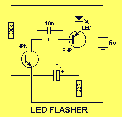
This is a very simple project using a printed circuit board and 8 components. It will flash an ordinary 3mm or 5mm (1/8" or 1/4") LED at a rate of about one flash per second. This circuit works on...

A low-cost, low-part-count MIDI to Trigger interface with 10 outputs. This MIDI to Trigger interface generates a TTL (5V) trigger signal for each note across a range of ten notes. It can be utilized, for instance, as a MIDI...

This application involves a static switch circuit where the control logic is implemented using a flip-flop, which is driven by a unijunction transistor. The flashing rate of the circuit can be adjusted, ranging from approximately 0.1 seconds to a...

The following method allows the timer to be triggered by a normally closed switch. This would be useful in applications such as intrusion alarms where the protection circuit is broken if a window or door is opened. Trigger Input...

LEDs are rated for a continuous current of only 30 mA, while this circuit operates them at approximately 50 mA. Although this is acceptable for low duty cycles with short pulses, the intended design has a high duty cycle....

A 100W full-wave single-junction transistor trigger control circuit designed for constant or variable speed control of a wire feed motor. The input control signal consists of a voltage adjusted by the master potentiometer (RPs) and a feedback voltage from...