
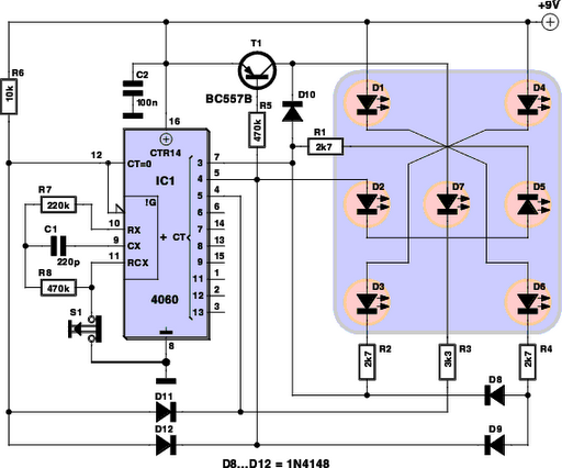
555 circuit for 8 leds flashing
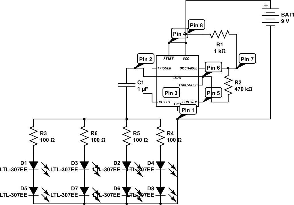
The circuit described involves the use of light-emitting diodes (LEDs) operating under specific current ratings. Standard LEDs typically have a maximum continuous current rating of 30 mA. In this design, the LEDs are driven at a higher current of approximately 50 mA, which is acceptable for low duty cycle applications but may lead to overheating or damage in high duty cycle scenarios. The output pin of the driving circuit is rated for a maximum output of 200 mA, which further complicates the design since operating close to this limit can lead to reliability issues.
To mitigate the risks associated with high current draw from the output pin, it is recommended to incorporate a transistor switch. The transistor will allow for higher current capacity while protecting the microcontroller or driving circuit from excessive load. The base of the transistor can be connected to the output pin, allowing it to control the LED current more safely.
The choice of resistors in this circuit is crucial. The original design uses a 470 KOhm resistor, which results in the LEDs being illuminated for approximately half the time, creating a flashing effect at a rate of slightly more than once per second. However, to achieve a more desirable flash rate, a 1 MOhm resistor is suggested. This change will slow down the charging time of the capacitor, thus controlling the blink rate of the LEDs more effectively.
Incorporating a diode across the resistor is also beneficial. This configuration allows the capacitor to charge rapidly through the 1K resistor while enabling a slower discharge through the 1 MOhm resistor. The result is a quick flash followed by an extended off period, which can be adjusted by experimenting with different resistor values. This flexibility allows for fine-tuning to achieve the desired visual effect of the LED flashing sequence.
Overall, careful consideration of component ratings and circuit design is essential to ensure the longevity and reliability of the LED circuit while achieving the intended operational characteristics.LEDs are rated at only 30 mA continuous, whereas this circuit runs them at around 50 mA. Not a problem for a low duty cycle with short pulses, but this circuit as you intend has a high duty cycle. Where you might run into a problem is that you`re right at the maximum capacity of the output pin (200 mA).
You might want to have the output pin drive a transistor to source the LED current. With the resistors you`ve selected, the LEDs will be on about half the time, and flashing a bit over once per second. This is why Rick recommends something more like a 1MOhm resistor, to slow the pulse rate down. What I would recommend is that you replace the 470 KOhm with a 1 MOhm and then put a diode across it.
This allows the cap to charge only through the 1K resistor, resulting in a very quick flash, followed by a relatively longer off period as the capacitor is forced to discharge through the 1M resistor. You should, of course, play around with the resistor values until you find a flash that is what you want,
🔗 External reference
Related Circuits
The team is highly interested in the design of a jammer circuit and has begun working on it. However, they are experiencing issues with the circuit, specifically that the signal is not being jammed effectively. The design of a jammer...
With the help of a simple ceramic piezoelectric detector, it is possible to assemble an interesting and useful impact sensor unit, which can be used to detect... An impact sensor unit utilizing a ceramic piezoelectric detector operates by converting mechanical...
This is a simple circuit diagram for a 150W power amplifier. The circuit can be constructed without a printed circuit board (PCB). The power output ranges from 100W to 150W, depending on the power supply and the Darlington transistors...
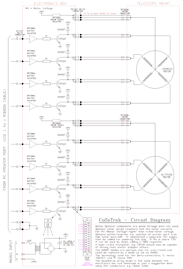
The back EMF voltage spikes produced by stepper motors, especially higher voltage motors, can damage a PC's printer port if connections are made incorrectly, flyback diodes are absent, or connected in reverse. The safest options are opto-isolated or buffered/inverted...
Every DIY enthusiast creates their own electronic dice using LEDs as indicators. This eliminates the need to physically roll dice; instead, a button is pressed. The circuit is designed to prevent any manipulation of the outcome, ensuring fairness. This...
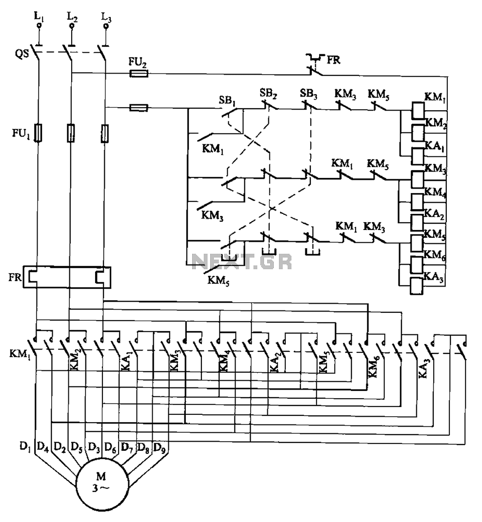
The circuit depicted in Figure 3-115 utilizes contactors and double buttons, allowing for speed conversion without the need to press the stop button. The buttons SBi, SBz, and SB3 correspond to high, medium, and low-speed operation, respectively. This circuit design...
Warning: include(partials/cookie-banner.php): Failed to open stream: Permission denied in /var/www/html/nextgr/view-circuit.php on line 713
Warning: include(): Failed opening 'partials/cookie-banner.php' for inclusion (include_path='.:/usr/share/php') in /var/www/html/nextgr/view-circuit.php on line 713