
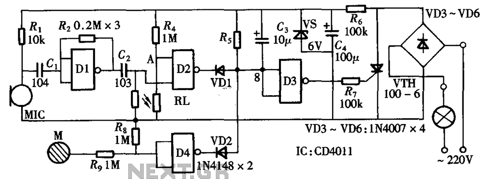
1 Kw flip-flop flasher circuit

The static switch circuit utilizes a flip-flop as its primary control element, allowing for the toggling of the output state in a reliable manner. The flip-flop can be configured in various modes, such as a bistable or monostable operation, depending on the specific application requirements. In this instance, the flip-flop is controlled by a unijunction transistor (UJT), which serves as a trigger device to initiate state changes.
The unijunction transistor is characterized by its ability to produce a sharp pulse output when a certain threshold voltage is exceeded. This pulse is used to toggle the flip-flop, thus controlling the switching action of the circuit. The timing characteristics of the circuit can be fine-tuned by adjusting the resistive and capacitive components connected to the UJT, which in turn modifies the charging and discharging cycles of the timing capacitor.
The adjustable flashing rate, which can range from 0.1 seconds to 10 seconds, is achieved through a variable resistor or potentiometer in conjunction with a timing capacitor. By changing the resistance or capacitance values, the time constant of the RC network can be altered, allowing for precise control over the frequency of the output signal. This flexibility makes the circuit suitable for various applications, including indicator lights, alarm systems, or any scenario requiring a timed on/off switching action.
Overall, the combination of a flip-flop and a unijunction transistor in a static switch circuit provides a robust solution for applications requiring controlled timing and switching capabilities. The design can be further enhanced by incorporating additional features such as LED indicators or output drivers to interface with other components in a broader electronic system.This is an application of the static switch circuit where the control logic is a flip-flop which is controlled by the unijunction transistor. The flashing rate can be adjusted from about 0,1 second to a 10 second cycle time.
Related Circuits
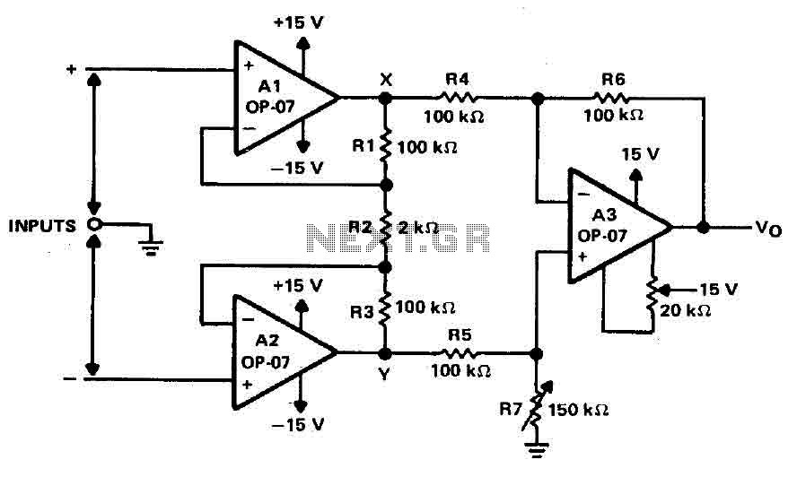
Operational amplifiers A1 and A2 are connected in a non-inverting configuration to form amplifier A3. The operational amplifier A3 can be classified as a subtractor circuit that converts the differential signal between the floating points X and Y into...
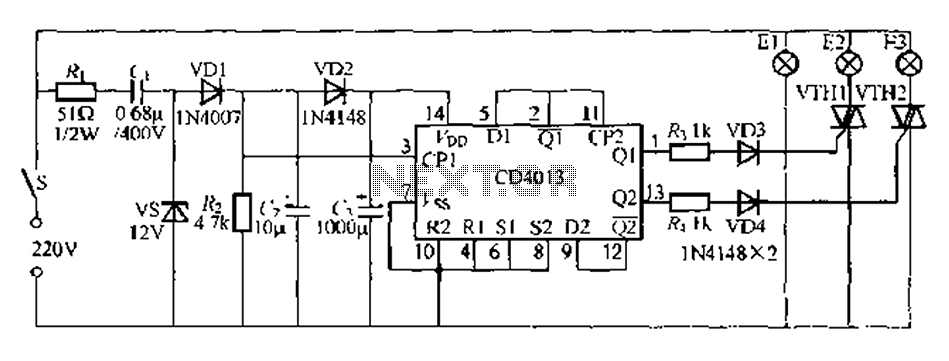
Figure 296 illustrates a control circuit that utilizes a switch (S) to manage three lamps (E1, E2, and E3) in a lighting system, suitable for controlling a chandelier in a living room. When the switch is off, all lights...
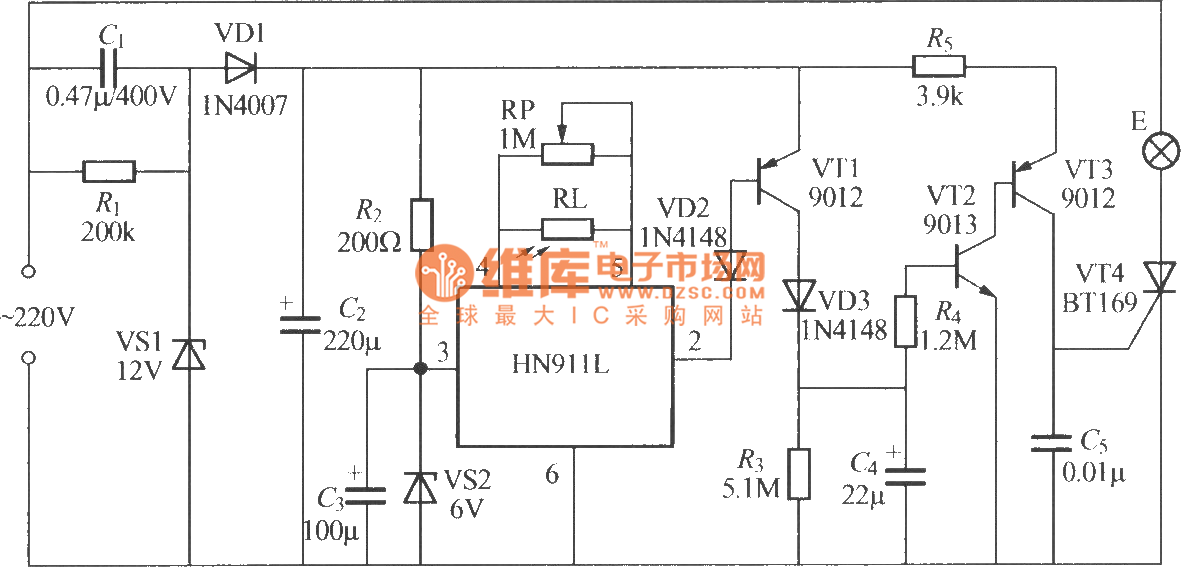
The figure illustrates an automatic light sensing system utilizing the HN911L pyroelectric infrared detection module. The HN911L incorporates high-sensitivity infrared sensors, a passive infrared (PIR) sensor, amplifiers, a signal processing circuit, and an output circuit. This module is capable...
4V flat monitor high voltage power supply circuit diagram. A wide range of 7 to 40V to 5V DC-DC step-down circuit diagram. Light control switch circuit diagram for safety. Circuit 555 constitutes a control circuit diagram for photoelectric applications. The...
The circuit integrates sound and light control with touch functionality, creating a fully operational delay section light switch circuit. It consists of light control, voice circuits, and a touch control circuit, all triggered by a thyristor switch. The described circuit...
Nissan Sentra 1.6 Liter Manual Transmission Starter Circuit Wiring Diagram. The Nissan Sentra 1.6 Liter manual transmission starter circuit wiring diagram provides a visual representation of the electrical connections involved in the starting system of the vehicle. This diagram is...