
flasher and lighting control circuits

The described circuit encompasses various functionalities, including pulse width modulation for hobby servos, DMX signal analysis, light dimming capabilities, and fluorescent lamp driving. The integration of a 555 timer for light dimming allows for precise control of incandescent bulbs, while the use of a PIC microcontroller enhances programmability and flexibility in controlling lighting systems. The safety considerations, such as the need for heat sinks and precautions against high voltages, emphasize the importance of proper circuit design and handling. Overall, the described circuits present versatile solutions for lighting control and signal processing in both hobbyist and professional applications.Hobby Servo`s Turn DMX signals into mechanical motion. Generally hobby servo`s require a pulse having a variable width from 1 to 2 milli seconds, with 1. 5mSec as the center position. The schematic below is a simple voltage to pulse width circuit. This is a simple O`scope trigger circuit for checking DMX signals. It is based on a 4528 CMOS monostable multivibrator. The "trigger" pot is adjusted first, untill a short pulse is generated near the end of the "BREAK" portion of the DMX signal. Then adjust the "delay" pot to zoom in on a portion of the signal. On DMX signals with few channels it works to trig the scope on the "trig" output, rather than the "delay" output.
This little circuit can be used to dim lights up to about 350 watts. It uses a simple, standard TRIAC circuit that, in my expirience, generates very little heat. Please note that this circuit cannot be used with fluorescent lights. Schematic is avialable here find in links, A number of people have been unable to find the transformer needed for the Black Light project, so I looked around to see if I could find a fluorescent lamp driver that does not require any special components. It uses a normal 120 to 6V stepdown transformer in reverse to step 12V to about 350V to drive a lamp without the need to warm the filaments.
Q1 must be installed on a heat sink. A 240V to 10V transformer will work better then the one in the parts list. The problem is that they are hard to find. This circuit can give a nasty shock. Be careful around the output leads. Disco anyone Actually, this strobe serves a much more useful purpose then making it look cool when you dance in the dark. You can use it to view fast moving objects, look for craks in PC boards (hold the strobe on the trace side of the board and look from the component side), and it is a great attention getter in a store window.
This Adjustable Strobe Light is the bigger brother of the plain old strobe light. This one uses a much more powerful "horse shoe" Xenon tube which produces more light. You can also control the flash rate up to about 20Hz. Do not look directly at the flash tube when this thing is on! The PIC is a self-contained microcontoller with oscillator, EEPROM, and RAM all built in. Mostany microcontroller will do, whatever you feel comfortable programming. I use MPLAB development software and a PICSTART PLUS programmer both from Microchip. The diode is only required for the polarity impaired like myself who may accidentally hook upthe battery backwards. You can short this connection out if you don`t feel like using a diode. 5 WATT FLUORESCENT LAMP MODULATION TEST CIRCUIT, NORMAL RUNNING VOLTAGE = 250V, SWITCH TO S FOR TWOSECONDS TO START LAMP, APPROX 10 WATTS OFPEAK MODULATED LIGHT, 5 WATT FLUORESCENT LAMP, DANGEROUS VOLTAGES EXIST ON ALL CIRCUITS, PULSE GENERATION CIRCUIT, LAMP DRIVER.
LINe filters for the power suplies. A light dimmer is a means of controlling the "brightness" level of an incandescent lamp, in this application we will use a 555 timer to control the brightness level of a low voltage incandescent bulb of up to 60 watts. The 555 timer "light dimmer" schematic circuit is shown in figure 1 below. For the light dimmer to work the 555 timer is configured as a "variable cycle", astable oscillator running some where around 300 Hz.
Light chaser Remotely controlled light dimmers in theatrical and architechtural applications use 0-10V control signal for controlling the lamp brightness. In this case 0V means that the lamp is on and 10V signal means that the lamp in fully on. A voltage between those values adjust the average voltage which is applied to the ligh bulb. This average voltage controlling is made by controllign the position in which phese the output triac fires (sooner it fires more power is applied to lamp).
PIC16F873 light controller Included are a couple of DOS programs that I used to generate the patternsand convert to an array rea 🔗 External reference
Related Circuits
A couple of motors were salvaged from an old printer, and there is uncertainty regarding how to connect them to a breadboard and subsequently to a Raspberry Pi. A cobbler kit for the Raspberry Pi is available for this...
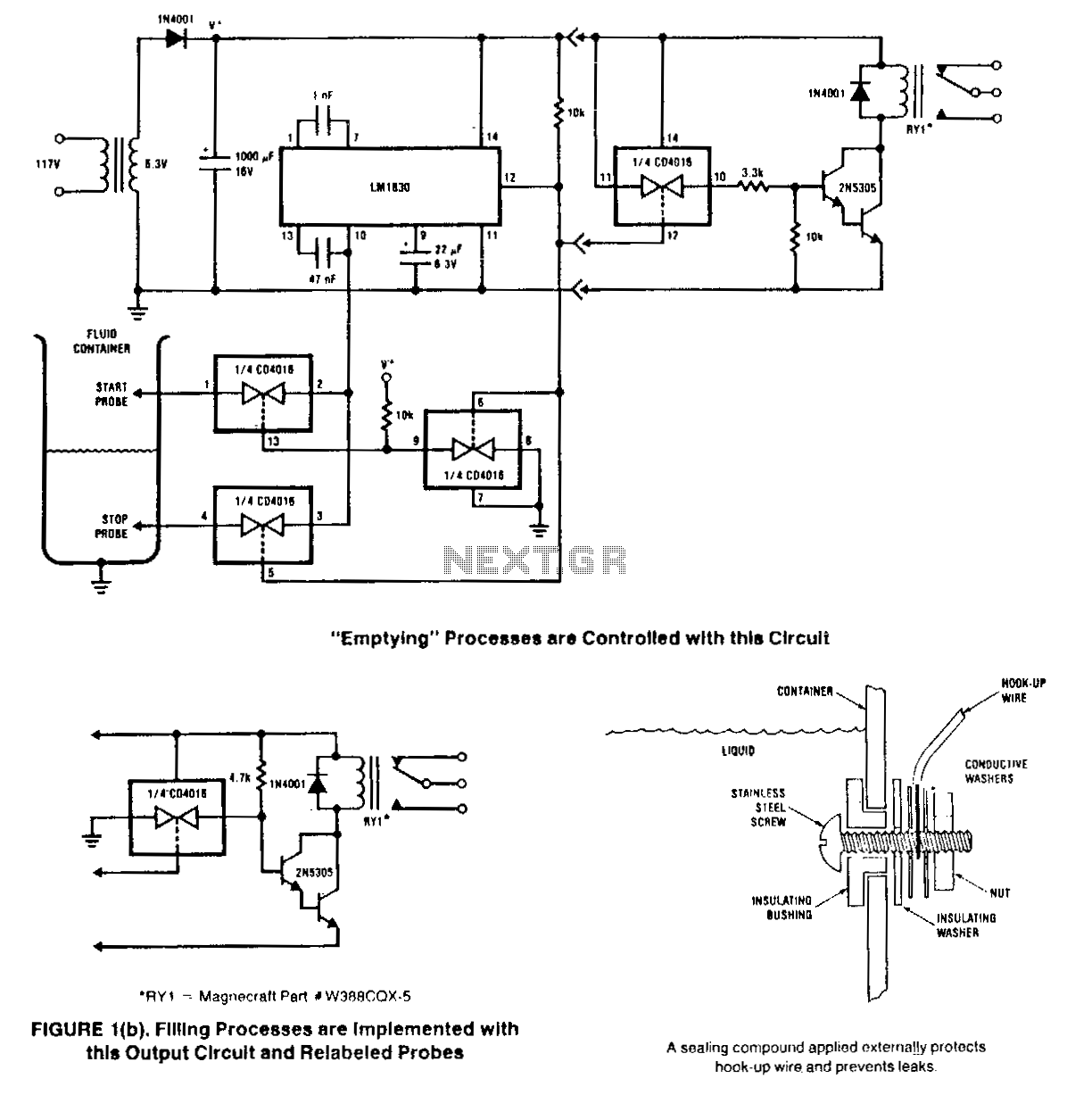
This circuit is designed to detect the presence or absence of aqueous fluids. An AC signal generated on-chip is passed through two probes within the fluid. A detector determines the presence of the fluid by using the probes in...
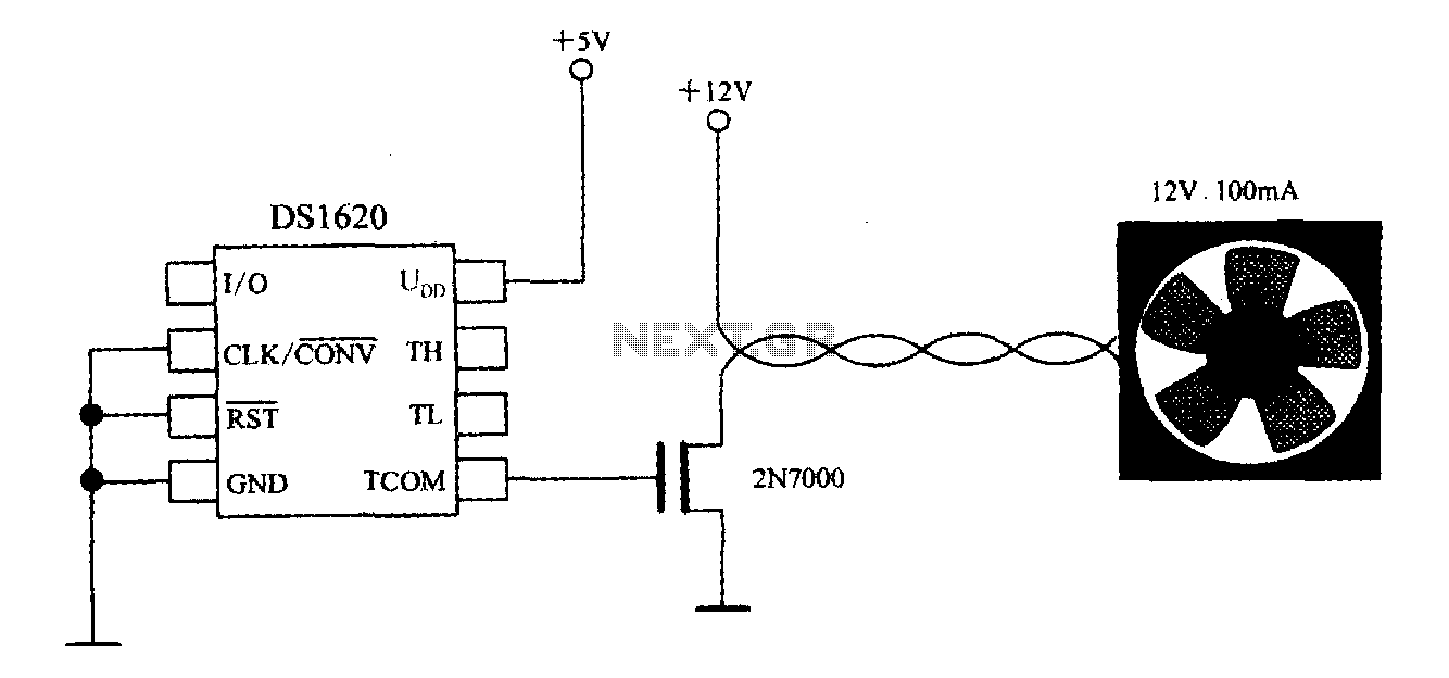
The DS1620, in conjunction with a microprocessor, is utilized to monitor temperature. By controlling the fan, the thermal conditions of the chip can be adjusted to establish a temperature control circuit as illustrated in the accompanying figure. The system...

The DC motor E inversion control circuit utilizes a loop configuration with various relay contacts. It employs a single set of normally open/normally closed relay contacts. When both inputs A and B are low, relay KI is activated. In...
This Project can be used with the three phase Induction motors. The circuit will take the full control of the motor and it will protect the motor from several faults such us over voltage and under voltage and the...
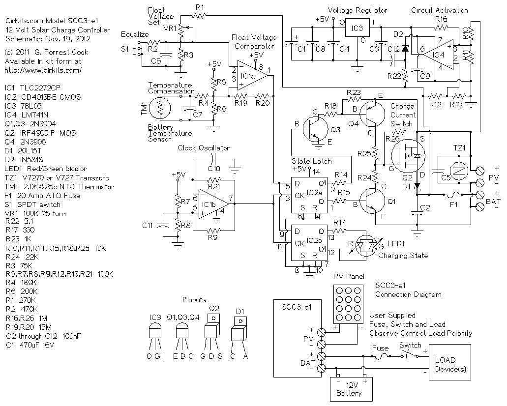
The SCC3 is a solar charge controller. Its function is to regulate the power flowing from a photovoltaic panel into a rechargeable battery. It features easy setup with one potentiometer for the float voltage adjustment, an equalize function for...