
How to connect a pulled motor from a printer to Breadboard and control with raspberry pi

To connect the salvaged motors to a breadboard and interface them with a Raspberry Pi, it is essential to first identify the type of motors. If the motors are DC motors, they will typically have two terminals and can be driven using a simple H-bridge circuit for direction control and PWM (Pulse Width Modulation) for speed control. On the other hand, if the motors are stepper motors, they will have multiple terminals, usually four, six, or eight, depending on the type of stepper motor.
For a DC motor setup, the following components are typically required:
1. H-Bridge Motor Driver: This component allows for the control of the motor's direction and speed. Common H-bridge ICs include the L298N or L293D.
2. Power Supply: Ensure that the power supply voltage matches the motor specifications.
3. Raspberry Pi GPIO Pins: These pins will be used to send control signals to the H-bridge.
4. Breadboard: For easy connections and prototyping.
The connection process involves:
- Connecting the motor terminals to the output pins of the H-bridge.
- Connecting the H-bridge inputs to the Raspberry Pi GPIO pins.
- Providing power to the H-bridge from an appropriate external power source.
- Using the Raspberry Pi's GPIO library to control the motor through the H-bridge.
For a stepper motor setup, a stepper motor driver, such as the A4988 or DRV8825, is recommended. The stepper motor driver will simplify the control of the stepper motor by managing the sequence of signals required to rotate the motor. The connection process includes:
- Connecting the stepper motor wires to the driver according to the motor's wiring configuration.
- Connecting the driver to the Raspberry Pi GPIO pins for step and direction control.
- Providing adequate power to the stepper motor driver from an external power source.
In both cases, it is advisable to consult the datasheets for the specific motors and drivers to ensure proper connections and configurations. Additionally, programming the Raspberry Pi to control the motors can be accomplished using Python with libraries such as RPi.GPIO or gpiozero. This will allow for precise control over motor movements and functionalities.I managed to salvage a couple of motors from a worn down old printer, and I`m unsure of how to get about connecting it to a breadboard and then to a Raspberry Pi. I`ve got a cobbler kit for my Pi that allows me to connect it up to the breadboard. I`m also unsure about what kind of motor it is, DC or Stepper. The motor looks like: 🔗 External reference
Related Circuits
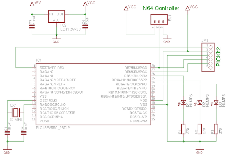
A few old N64 controllers were found, and the idea is to use them to control other devices. This document outlines the detailed steps taken to achieve this. A PIC microcontroller was utilized, although the code can be adapted...
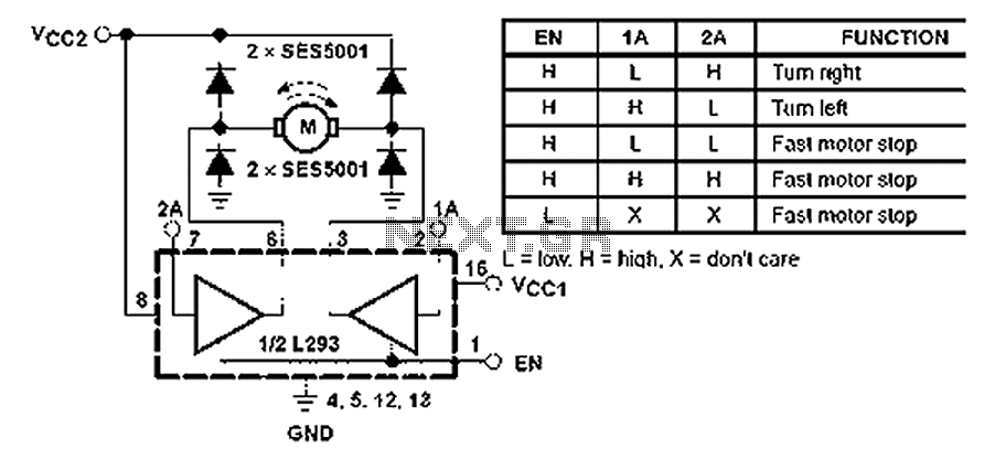
All inputs are compatible with TTL. Each output consists of a complete totem pole driver circuit, utilizing Darlington transistors and pseudo-Darlington sources. The driver enable signals, labeled as 1,2 EN and 3,4 EN, control the activation of drivers 1...
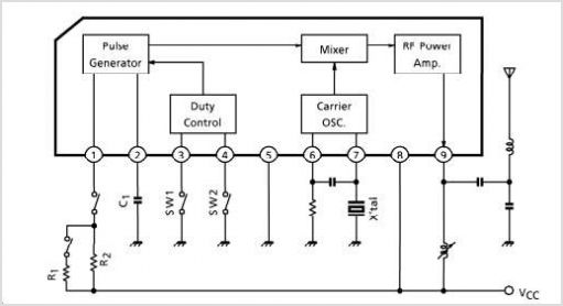
TB6556FG is a 3-phase full-wave sine-wave PWM brushless motor controller. It features sine-wave PWM control and includes a built-in triangular-wave generator with a carrier cycle defined as fosc/252 (Hz). The device also offers a built-in lead angle control function...
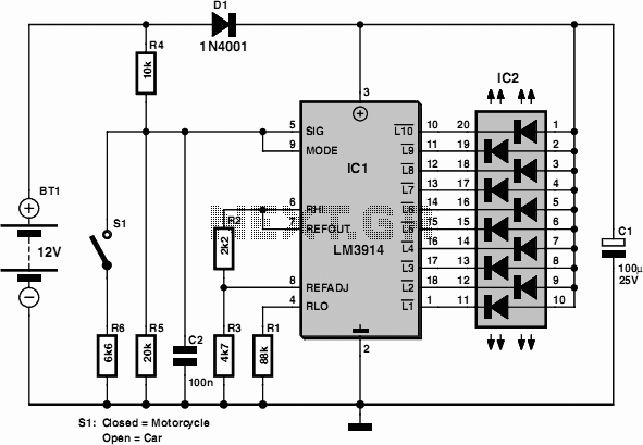
Car and Motorcycle Battery Tester Circuit. Going camping today often requires bringing various electronic devices for daily activities or entertainment. Typically, a charged lead-acid battery and a power source are essential. The Car and Motorcycle Battery Tester Circuit is designed...
The simplest solution for implementing joystick control for a robot is to program the actions in software on a microcontroller. However, many users prefer off-the-shelf components, thus this circuit is designed using diodes, resistors, transistors, and a FAN8200 motor...
This preamplifier was designed as a stand-alone portable unit, useful to control the signals generated by guitar pick-ups, particularly the contact "bug" types applied to acoustic instruments. Obviously it can be used with any type of instrument and pick-up....