
Thermostat with three-wire serial interface smart temperature sensor DS1620 configuration control circuit

The DS1620 temperature sensor is designed for precise temperature monitoring and is integrated with a microprocessor to facilitate real-time temperature control. The microprocessor processes the temperature data from the DS1620 and generates control signals based on predefined temperature thresholds. The TCOM signal is pivotal in this setup, as it directly influences the operation of the fan through the 2N7000 MOSFET.
When the temperature reading from the DS1620 exceeds the upper threshold (tH), the microprocessor sends a signal to the TCOM pin, activating the MOSFET. This action closes the circuit, allowing current to flow through the fan, which initiates cooling. The fan continues to operate as long as the temperature remains above the lower threshold (tL). Once the temperature drops below this threshold, the microprocessor deactivates the TCOM signal, turning off the MOSFET and consequently the fan.
The 2N7000 MOSFET is well-suited for this application due to its specifications, which allow it to handle the necessary current and voltage levels without overheating. In scenarios where a higher cooling capacity is required, the 2N7010 MOSFET can be utilized, which offers enhanced performance characteristics suitable for larger fans.
This temperature control circuit is essential for maintaining optimal thermal conditions in electronic devices, thereby enhancing reliability and performance. The integration of the DS1620 with a microprocessor and MOSFETs exemplifies efficient thermal management in electronic systems.DS1620 with a microprocessor to monitor temperature, by opening or closing the fan can be changed thermal conditions of the chip to achieve temperature control circuit as shown in FIG. Which is characterized TCOM signal through 2N7000 type MOSFET, to control the fan, the chip surface temperature t Open the fan when tH, and maintained until t
Related Circuits
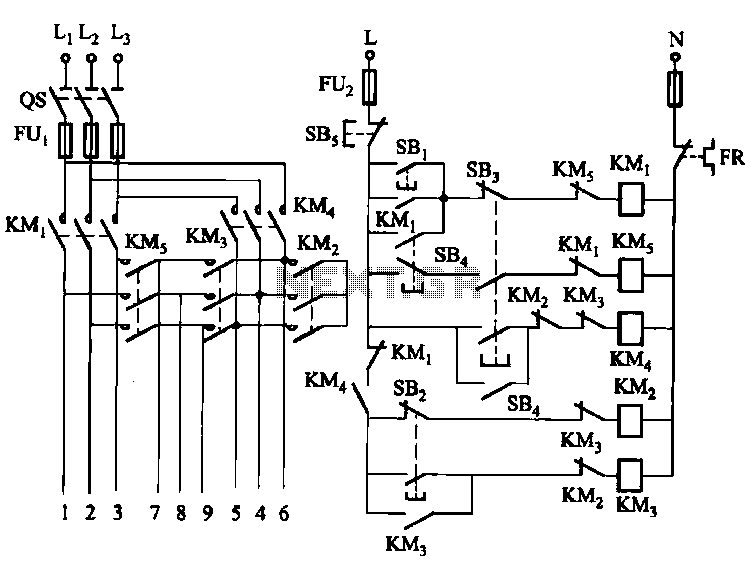
The circuit illustrated in Figure 3-62 is a manually controlled step-down start button circuit. Upon startup, the initial motor windings are configured in a Y-shape. Subsequently, the configuration transitions to a Yanbian shape (2:1), followed by a Yanbian shape...
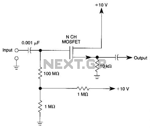
Biasing methods for an N-channel MOSFET to form a unity-gain noninverting amplifier or source-follower. The N-channel MOSFET can be utilized in various configurations, with one common application being the unity-gain noninverting amplifier, also known as a source-follower. In this configuration,...

This is a circuit design for a doorbell that produces a bird-like sound. The circuit is controlled by an NPN transistor. The operation of the circuit begins when P1 is set to an experimental value, starting with approximately 220...
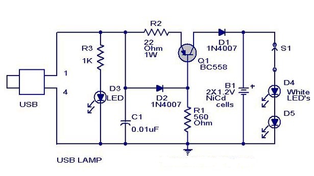
A simple USB-powered lamp designed to illuminate a desktop during power outages. The circuit operates at 5 volts sourced from a USB port. The 5V from the USB is directed through a current-limiting resistor (R2) and a transistor (Q1)....

This circuit is similar to the one found in the Single Buss 1V/Octave Keyboard Controller. Refer to the circuit description there for more details. This board includes additional resistors used in the keyboard voltage divider. In a typical keyboard,...
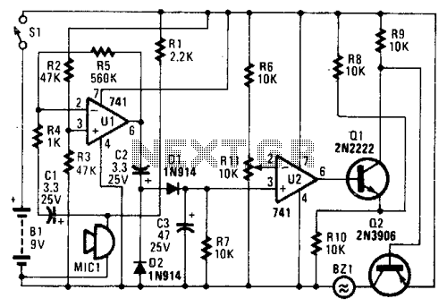
In the circuit, U1 amplifies the audio captured by the condenser microphone. Resistor R1 limits the current, while R2 and R3 center the amplifier's output to a voltage level of %B+ to facilitate the use of a single-ended power...