
FlasherCircuit using NE 555 IC for Lamp

The lamp flasher circuit utilizes a standard NE555 timer IC, which is a versatile component widely employed in timing applications. In this configuration, the NE555 operates in astable mode, meaning it continuously oscillates between its high and low states, producing a square wave output. The frequency of this oscillation, and therefore the flashing rate of the lamp, can be adjusted by changing the resistance values of R2 and R3, as well as the capacitance of the timing capacitor connected to the discharge pin.
Diodes D1 and D2 serve a crucial role in providing a stable power supply to the NE555 IC. They rectify the AC mains voltage, ensuring that the IC receives a consistent DC voltage necessary for proper operation. The half-wave rectification allows only one half of the AC waveform to pass through, which is then smoothed out by a filtering capacitor (not explicitly mentioned but typically included in such designs) to provide a more stable voltage.
Transistor T1 acts as a switch that controls the flow of current to the triac, BT136. When the NE555 produces a high output, T1 is activated, allowing current to flow through the gate of the triac. The triac, once triggered, allows current to pass through the load (the lamp), enabling it to flash. Resistor R4 is essential as it limits the base current to Q1 (the transistor), protecting it from excessive current that could lead to damage.
Overall, this circuit effectively demonstrates the principles of timing, rectification, and control using common electronic components, making it suitable for various lighting applications where flashing effects are desired. The design is versatile, allowing for adjustments to the flashing rate, making it adaptable for different lamp types and user preferences.This is the circuit diagram of lamp flasher operated from mains. By this you can flash up to 200 Watt lamps at rates determined by you. IC NE555 is wired as an astable multivibrator for producing the pulses for flashing the lamp. The flashing rate can be set by the value of resistors R2 & R3. Diodes D1 & D2 provides a half wave rectified regulated supply for the IC. Transistor T1 is used to drive triac and triac BT136 for driving the load. Resistor R4 limits the base current of Q1. 🔗 External reference
Related Circuits

The circuit illustrated below represents a simple thermometer circuit based on the LM335 temperature sensor. This circuit comprises two main components: the LM335 sensor and its adjustment circuitry. The output from the LM335 generates a voltage of 10 millivolts...
Here is the schematic diagram for a 20 Watt driver. I developed this circuit in 1985, and used it to build a lamp that found much use both as camping light and as emergency light during the then-frequent power...
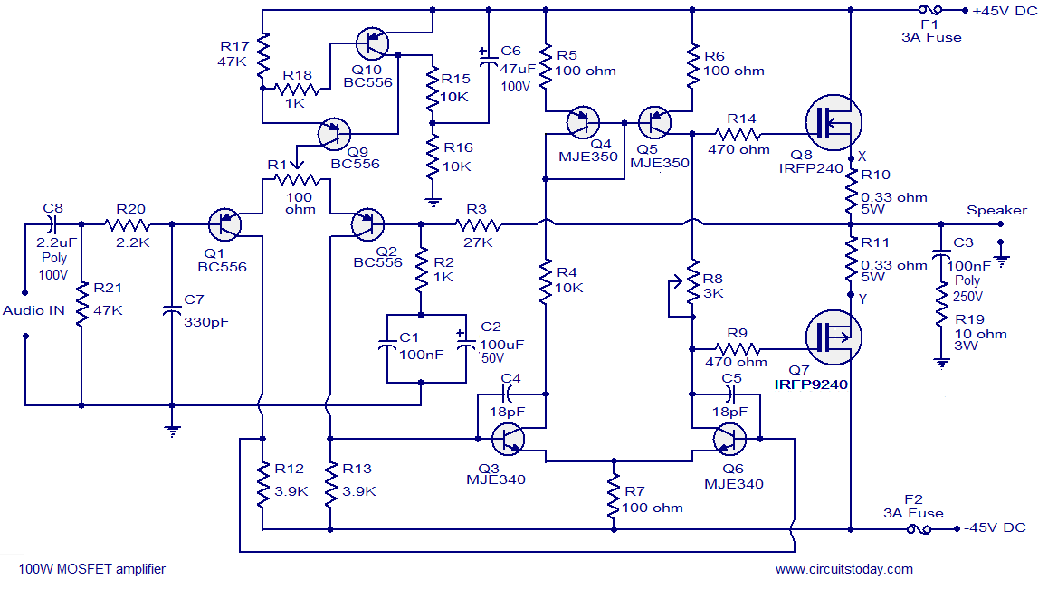
Hi-fi 100W MOSFET power amplifier circuit. Operates from a 45V dual supply. Delivers 100W to an 8-ohm speaker and 160W to a 4-ohm speaker, with low distortion. The Hi-fi 100W MOSFET power amplifier circuit is designed to provide high-quality audio...
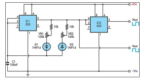
This circuit allows for the independent variation of the on/off times of a 555 timer across a wide range. This capability is not achievable with a conventional 555 timer circuit. The described circuit enhances the functionality of the standard 555...
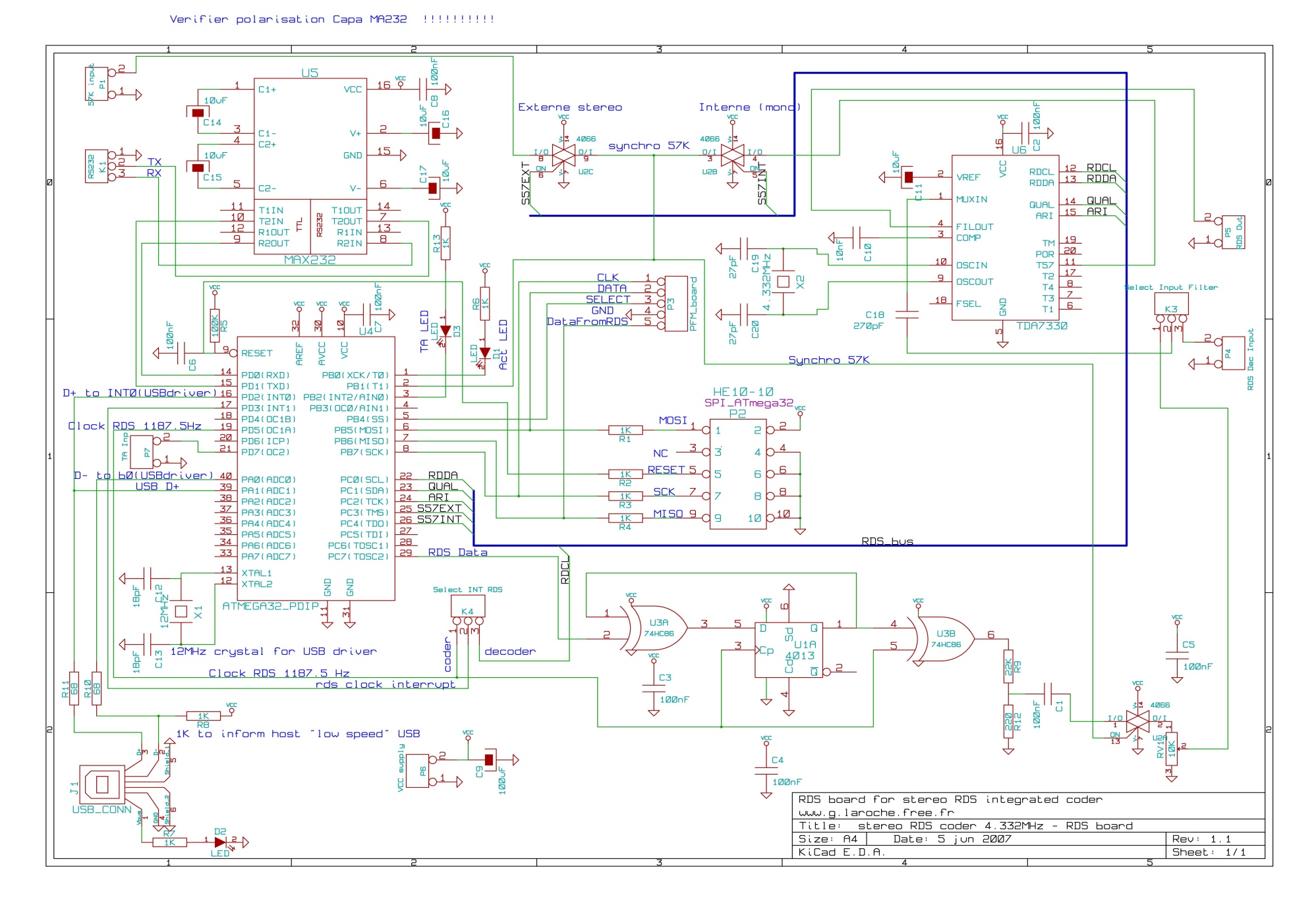
This board is an RDS coder utilizing an ATMEL AVR ATmega32 microcontroller. It can be controlled via an RS232 link, USB interface, or SPI. TA data is displayed with an LED and can be controlled through hardware input, RS232,...
.jpg)
The HID ballast circuit consists of a buck stage for regulating lamp current and power, a full-bridge output stage that generates a low-frequency (200Hz) AC square-wave voltage and current to drive the lamp, and an ignition circuit that produces...