
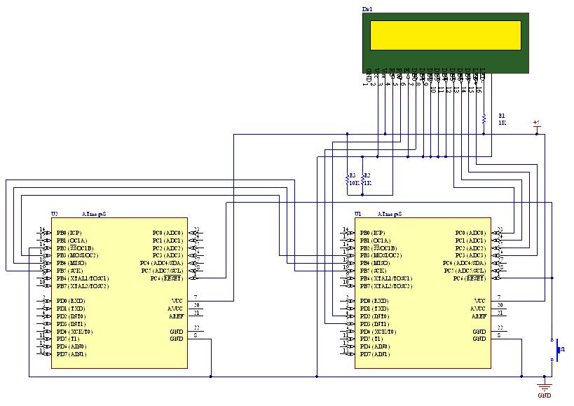
USB RDS Coder Board using ATmega32

The RDS (Radio Data System) coder is designed to encode and transmit additional data alongside traditional FM radio broadcasts. The core of the system is the ATMEL AVR ATmega32 microcontroller, which provides the necessary processing power and control capabilities. This microcontroller features a 16 MHz clock speed, 32 KB of flash memory, and various input/output pins that facilitate interfacing with other components.
Control options for the RDS coder include RS232, USB, and SPI. The RS232 interface allows for serial communication with external devices, enabling configuration and data transmission. The USB interface offers a more modern and versatile connection option, allowing for easier integration with computers and other USB-capable devices. The SPI (Serial Peripheral Interface) is mentioned as a future enhancement, which will enable high-speed communication with other peripherals.
The board's functionality includes the display of Traffic Announcement (TA) data via an LED indicator, providing a visual signal to users when a TA message is being transmitted. The control methods for this data display include direct hardware input, which allows for manual operation, as well as through the RS232 and USB interfaces for automated or remote control.
Future enhancements for the board could include the implementation of the SPI interface, which would allow for additional peripheral connections, expanding the overall functionality and flexibility of the RDS coder. This could also enable the integration of more advanced features, such as real-time data processing and improved user interface options.This board is a RDS coder using an ATMEL AVR ATmega32. This board can be controled by a RS232 link, USB interface or SPI. TA data is displayed wiyth a LED and can be controled by : - Hardware input - RS232 - USB - SPI (not yet implemented).. 🔗 External reference
Related Circuits
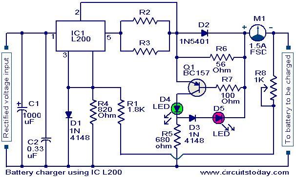
A simple battery charger circuit with reverse polarity indication is presented here. The circuit utilizes the L200 integrated circuit (IC), which is a five-pin variable voltage regulator. The charging circuit can be powered by DC voltage from either a...
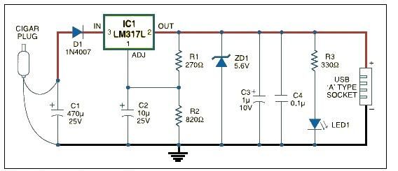
This USB car charger adapter project functions as a DC-DC power converter that effectively converts the 12V car battery voltage into a stable 5V output. It is designed to supply power from a car's cigar lighter socket to any...
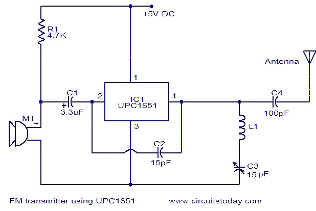
The circuit diagram of an FM transmitter utilizes the IC UPC1651, which is a wideband UHF Silicon MMIC amplifier. This integrated circuit features a broad frequency response of up to 1200 MHz and a power gain of up to...
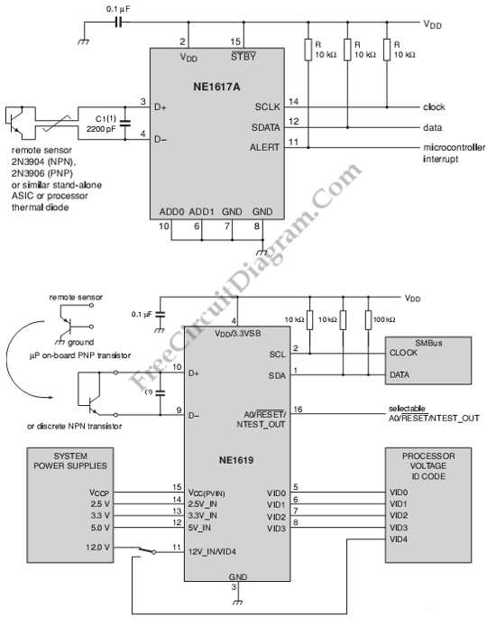
This is a circuit of a board system monitoring the temperature and voltage conditions. It uses the NE1617A, which is a 2-channel temperature sensor. The described circuit serves as a monitoring system for both temperature and voltage conditions, utilizing the...
This document outlines the process of transmitting data between a PC and an AVR Atmega8 microcontroller using the USART module. The communication utilizes the COM port of the PC, which is based on the RS232 protocol, and the UART...
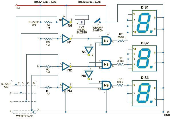
This schematic outlines a straightforward electronic project for designing a water level indicator circuit. It employs a 7-segment display to represent water levels in a tank as low, half, and full, indicated by the letters L, H, and F,...