
Flashing Light with Triacs

The flashing light circuit is designed to create a visual indication through intermittent illumination, which can be adjusted in frequency to suit various applications. At the core of the circuit are triacs, which are semiconductor devices capable of controlling power. They allow the circuit to switch on and off rapidly, producing the desired flashing effect.
The D1 diode serves a critical function in this circuit by providing rectification, ensuring that the current flows in a single direction. This is essential for the proper operation of the triacs, as they require a specific polarity to function effectively. The semi-adjustable resistor, often a potentiometer, allows for fine-tuning of the circuit's frequency. By adjusting this resistor, the user can change the amount of current flowing through the circuit, thereby altering the flashing rate of the light.
The circuit may also include additional components such as capacitors or resistors to stabilize the operation and enhance performance. Capacitors can be used to filter out noise and provide a smoother operation, while resistors can limit current to protect sensitive components.
In summary, this circuit is a versatile solution for creating variable frequency flashing lights, suitable for applications ranging from decorative lighting to signaling devices. The use of triacs, along with the diode and adjustable resistor, ensures efficient operation and customization of the flashing frequency.This flashing light circuit uses triacs to generate an intermittent light with variable frequency. Additional components are the D1 diode and semi adjustab.. 🔗 External reference
Related Circuits
The turn signals, hazard lights, stop lights, and headlights are functioning properly. However, the tail lights do not operate when the headlights are on. The bulbs appear to be in good condition, as they were tested by switching the...
The schematic depicts standard light bulbs, indicating the possibility that some bulbs may be burned out. It is currently unclear whether the bulbs can be easily replaced. Further inspection reveals that the bulbs in the HVAC control can indeed...
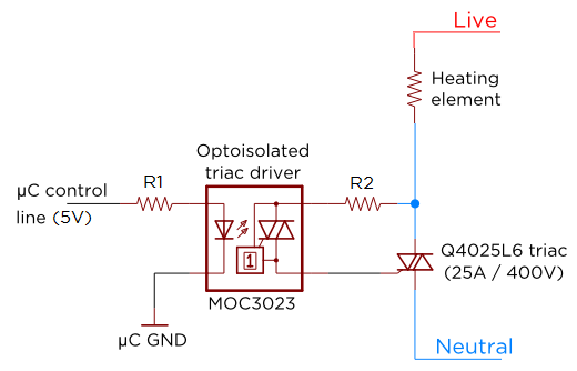
Several individuals have requested clarification on calculating resistor values for a triac circuit. This information may be beneficial for adapting the Sous Vader for custom builds. The circuit in question involves the resistor values R1 and R2 in an...

This is a simple automatic light switch circuit designed for bedrooms. After construction, connect the input terminals of this circuit in parallel to the internal buzzer terminals of a quartz alarm clock. When the clock alarm is activated, the...
Toyota MR2 Exterior Lights Wiring Diagram Manual PDF Download. The Toyota MR2 Exterior Lights Wiring Diagram Manual provides a comprehensive guide for understanding the wiring configurations associated with the exterior lighting system of the Toyota MR2 model. This manual is...
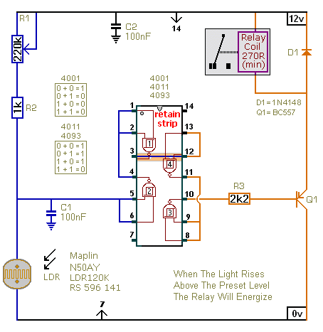
The first circuit energizes the relay when the light rises above the preset level. The second circuit energizes the relay when the light falls below the preset level. The two circuits are practically identical. The only difference between them...