Quartz Controlled Bedroom Light Switch

This is a simple automatic light switch circuit designed for bedrooms. After construction, connect the input terminals of this circuit in parallel to the internal buzzer terminals of a quartz alarm clock. When the clock alarm is activated, the circuit will control the lighting.
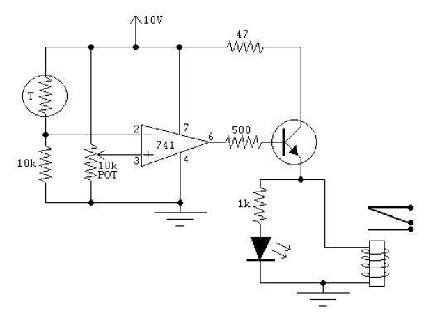
The circuit operates by utilizing the signal from the quartz alarm clock's internal buzzer to trigger the automatic light switch. The primary components typically involved in this setup include a relay, a transistor, and a few passive components such as resistors and capacitors.
When the alarm sounds, the voltage from the buzzer is fed into the base of a transistor, which acts as a switch. The transistor is configured in a way that it allows a larger current to flow from the collector to the emitter when the base receives a small current from the buzzer. This action energizes a relay coil connected to the circuit, which mechanically closes the switch contacts of the relay.
The relay contacts can be connected to a light fixture or another load, allowing the light to turn on automatically when the alarm is triggered. Additionally, a diode may be placed in parallel with the relay coil to prevent back EMF, which could damage the transistor when the relay is de-energized.
In terms of power supply, it is essential to ensure that the circuit operates within the voltage ratings of the components used. If the alarm clock operates on a low voltage, such as 5V or 12V, the circuit should be designed accordingly to avoid damage to the components.
Overall, this automatic light switch circuit provides a convenient solution for automatically illuminating a bedroom at a predetermined time, enhancing both functionality and comfort.Here is an ultra simple automatic light switch circuit for bedrooms. After construction,connect the input terminals of this circuit in parallel to the internal buzzer terminals of a Quartz-Alarm Clock. When the clock alarm is activated at a.. 🔗 External reference


