
Flip-Flop Independent Lamp Driver

The described circuit utilizes two silicon-controlled rectifiers (SCRs), SCR1 and SCR2, in a configuration that allows for the control of the charge state of capacitor CI through the manipulation of switches S1 and S2. Initially, with SCR1 conducting and SCR2 non-conducting, capacitor CI charges fully, establishing a positive voltage at its LMP2 terminal.
When switch S2 is pressed, SCR2 is triggered into conduction, which in turn causes SCR1 to turn off. This occurs through a capacitive coupling effect, where the anode of SCR2 influences the gate of SCR1, effectively interrupting its conduction path. The transition results in capacitor CI discharging and then recharging in the opposite polarity, with the left terminal becoming positive.
Subsequently, the circuit can be reverted to its original state by pressing switch S1. This action activates SCR1 via its gate, allowing it to conduct again. Simultaneously, SCR2 is turned off through a similar capacitive coupling mechanism, thus restoring the initial charge state of capacitor CI.
This circuit configuration exemplifies a bistable multivibrator operation, where the state of the circuit can toggle between two stable states based on the input from the switches. The design is efficient for applications requiring controlled charge and discharge cycles, such as in timing circuits, pulse generation, or energy storage systems. The use of SCRs provides robust control over high-power applications, ensuring reliable operation under varying load conditions. Assume first that SCR1 is on and SCR2 is off so that CI is fully charged, with its LMP2 end positive. The state of the circuit can be changed by pressing S2. As SCR2 turns on, it turns SCR1 off capacitively via its anode. Capacitor CI then recharges in the opposite manner (i.e., the left end is now positive). The state of the circuit can be changed again by pressing SI, thus driving SCR1 on by way of its gate, and driving SCR2 off capacitively via its anode.
Related Circuits
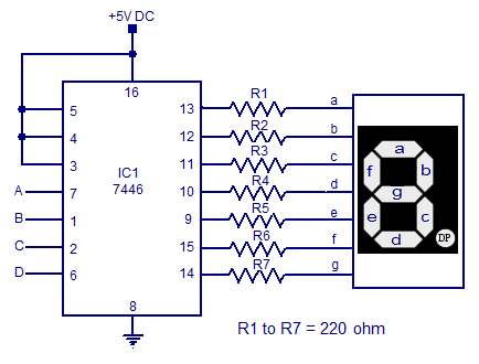
7-segment display driver circuit based on the 7446. This circuit includes a seven-segment display system and a 7-segment decoder/driver, capable of sinking and sourcing current for the display. The 7446 is a BCD (Binary-Coded Decimal) to 7-segment latch/decoder/driver that facilitates...
The ICL7665S Super CMOS Micropower Over/Under Voltage Detector features two low-power, individually programmable voltage detectors integrated on a single CMOS chip. It typically requires 3 µA for operation and is designed for battery-operated systems and instruments that need high...
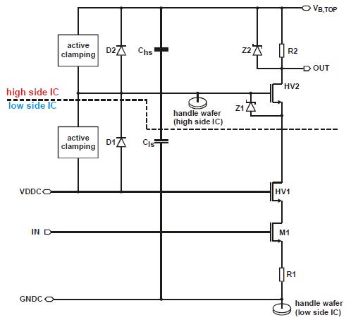
Integration of 1200V SOI gate driver ICs into a medium power IGBT module package. A novel approach for medium power applications. The integration of 1200V Silicon-On-Insulator (SOI) gate driver Integrated Circuits (ICs) into medium power Insulated Gate Bipolar Transistor (IGBT)...
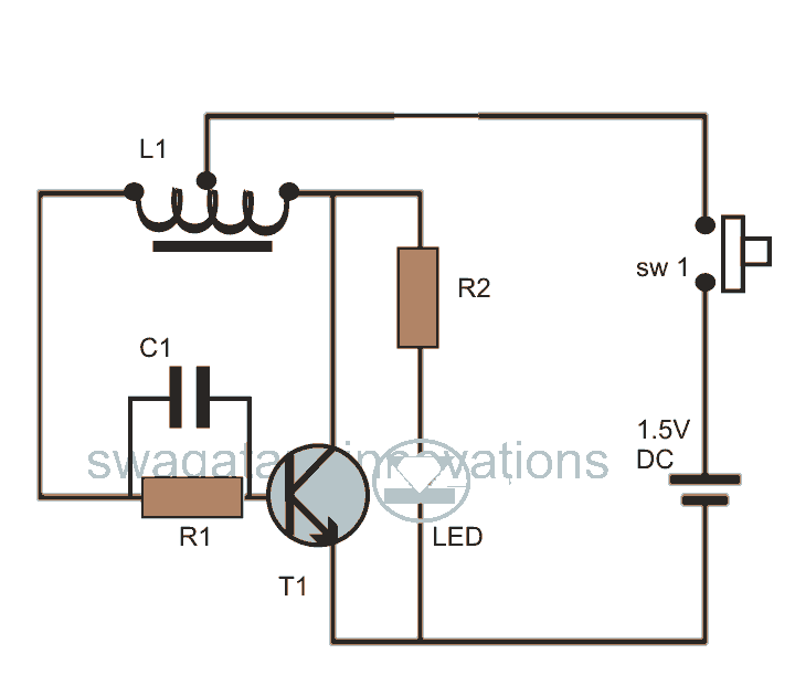
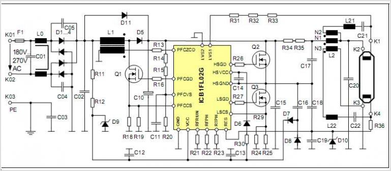
This post discusses blue and white LED drivers utilizing a joule thief circuit. Further exploration of the circuit's functionality is provided, along with simulation points. The joule thief circuit is a simple and efficient boost converter that allows for the...
The circuit provides sufficient illumination suitable for reading purposes. Capacitor CX, in conjunction with diodes D1 through D4, constitutes the AC step-down circuit. CX lowers the high voltage AC from the mains to a low voltage AC, which is...
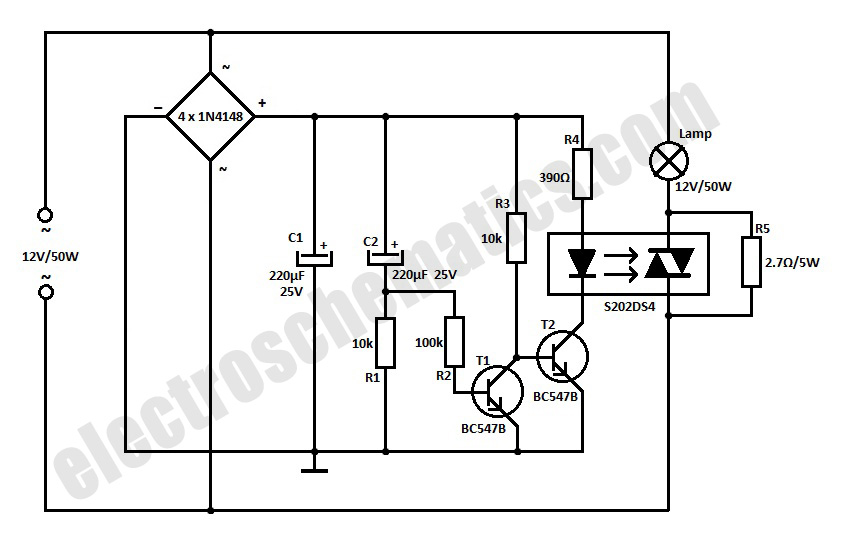
This simple 12-volt halogen lamp soft starter circuit extends the life of the halogen lamps by eliminating the sharp rise in the temperature of the filament. The 12-volt halogen lamp soft starter circuit is designed to mitigate the initial surge...