
Fluid Level Detector Circuit PCB

The fluid level indicator circuit is designed to provide a clear and intuitive representation of liquid levels in a tank or reservoir. The seven-segment display is utilized to show five distinct states of fluid levels, enhancing user understanding through the use of recognizable letters. The letters displayed correspond to specific fluid levels: 'E' indicates an empty tank, 'L' signifies a low level, 'H' represents a half-full condition, 'A' denotes an above-average level, and 'F' indicates a full tank.
The core of the circuit is based on two CMOS ICs: the CD4001, which is a quad 2-input NAND gate, and the CD4055, which functions as a BCD to seven-segment decoder/driver. The CD4001 is used for logical operations that determine the current fluid level based on input from sensors placed at different heights within the tank. These sensors can be float switches or conductive probes that detect the presence or absence of liquid.
The CD4055 takes the binary-coded decimal (BCD) input from the logic gates and converts it into a format suitable for driving the seven-segment display. This IC is particularly advantageous due to its ability to handle both numerical and alphabetic outputs, making it ideal for this application. The BCD codes needed to display the letters are specified in a reference table, which maps the input signals to the corresponding outputs on the display.
Power efficiency is a crucial aspect of this circuit. The use of CMOS technology ensures that the circuit consumes minimal current, which is especially beneficial for battery-operated devices. This low power requirement allows the fluid level indicator to operate for extended periods without the need for frequent battery replacements, enhancing its practicality in various applications.
In summary, this fluid level indicator circuit provides a user-friendly method for monitoring liquid levels, utilizing a combination of CMOS technology and a seven-segment display to convey information clearly and efficiently. The design is suitable for various applications where fluid level monitoring is essential, including water tanks, chemical reservoirs, and other liquid storage systems.Here is the circuit of a fluid level indicator which shows each level in meaningful English letters. The circuit presented here using seven segment display to display the letter E for empty, L for low, H for half, A for above average, and F for full tank. The circuit is comprised of CMOS IC`s CD4001, CD4055 and a 7 segment display driver. The dec oder IC is capable of displaying the English letters besides the usual digits 0 through 9 to disply fluid levels. The BCD codes for various displays are given in Table. The CMOS IC`s make current consumption extremely low so we can power the circuit from a battery. 🔗 External reference
Related Circuits

The danger always exists when fuel gases such as propane or natural gas are confined to a small area. The toxic gas alarm utilizes a tin-oxide semiconductor. A coil of thin wire is heated by a 12 V battery...
In applications where a MOSFET is employed to switch a load, incorporating short-circuit or overload protection is straightforward. This can be achieved by utilizing the internal resistance RDS(ON) of the MOSFET, which generates a voltage drop proportional to the...
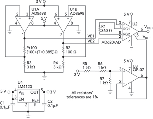
Bridge circuits are widely used for conditioning signals from resistive sensors. These circuits are sensitive to minor changes in resistance, providing a differential output from a single current or voltage source. However, the sensors connected to a passive bridge...
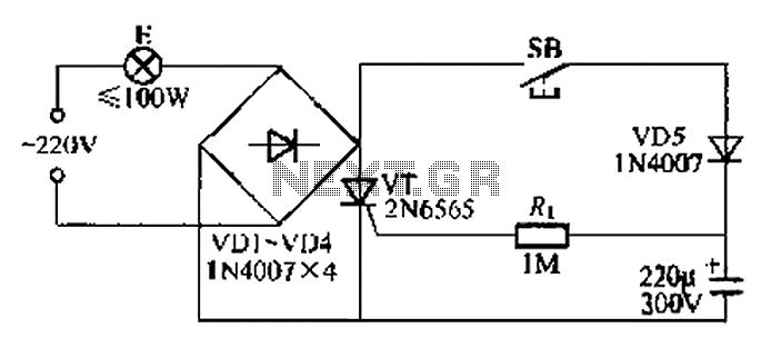
This circuit is a simple connection delay lamp circuit. When the lights are turned on and the switch is pressed, the power supply is activated. The capacitor charges rapidly, causing the thyristor (VT) to open, which in turn lights...

This circuit is designed for rapid battery charging. It is recommended for those who require a faster charger. The charger operates at a low temperature of 5 degrees Celsius. The input voltage is 15 volts DC, while the output...
The goal is to utilize a PC to measure the outdoor temperature using a serial-connected device equipped with a probe that can be conveniently placed outside. Although various options were found through online searches, many appear to be overly...