
Simple light delay circuit 3

This connection delay lamp circuit utilizes a thyristor to control the illumination of a lamp based on the charge and discharge cycle of a capacitor. The circuit's operation begins when the power supply is activated by pressing the switch (F SH). The capacitor (C) charges rapidly through the power supply, and once the voltage across the capacitor reaches the triggering threshold of the thyristor (VT), it turns on, allowing current to flow through the lamp (E). This initial state keeps the lamp illuminated.
The stored charge in the capacitor is then discharged through a resistor (R) connected to the thyristor's gate. This discharge maintains the thyristor in its conductive state, allowing the lamp to remain lit even as the capacitor begins to release its stored energy. The duration for which the lamp stays illuminated depends on the capacitance value and the resistance in the circuit, which can be adjusted to achieve the desired delay.
As the capacitor discharges, its voltage drops. Once the voltage falls below the thyristor's holding current, the thyristor turns off, typically occurring when the alternating current waveform crosses zero. At this point, the lamp (E) turns off, completing the delay cycle.
The choice of thyristor is critical in this design. Thyristors such as the 2N6565 and MCR100-8 are recommended due to their micro-triggering capabilities and unidirectional conduction properties. The resistor value can be fine-tuned to modify the delay time, allowing flexibility in the circuit's response.
It is important to select a capacitor with an adequate voltage rating, specifically at least 300V, to ensure reliable operation. An electrolytic capacitor is preferred for this application, but care must be taken to prevent leakage currents, which can lead to premature lamp shutdown. Proper circuit design and component selection will ensure consistent performance and longevity of the delay lamp circuit.Another simple connection delay lamp circuit. Turn on the lights, press F SH, power supply by SH, VD. The capacitor (rapid charging, thyristor VT opened, lamp E lights up. Loos en SI3, capacitance (1 stored charge to the discharge electrode through the resistor R VT doors, so can maintain normal VT opened, the lamp E is still in the light emitting state when the charge is substantially C after release, VT trigger the loss of current, alternating current passes through zero ie when Ge off, turn off the lamp E. VT can be 2N6565, MCR100-8 type products and other micro-triggered thyristor unidirectional, shame get longer Q delay.
R or decrease (numerical called latency canthus Quine section of the circuit. withstand voltage of the capacitor C still needs to use an electrolytic capacitor to 300V in Bong circuit, electrolytic capacitor leakage current can cause the size of small lights off now dead elephant, the female energy is better than Lai inverted front.
Related Circuits
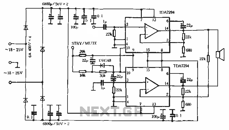
Europe's leading SGS-THOMSON STMicroelectronics recently introduced a new power integrated amplifier, the TDA7294, to the Chinese mainland market. This amplifier, characterized by a cold and hard tone, is particularly suited for Hi-Fi applications such as home theaters and active...
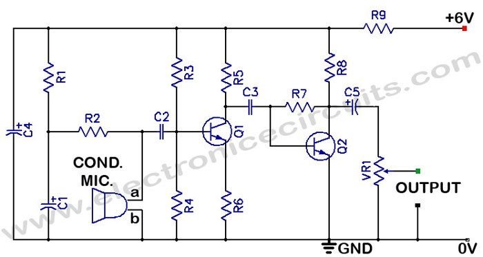
There is often a need for a sensitive sound pickup device, which can be utilized as a simple microphone or for more specialized applications such as a sound-operated alarm, a bugging device, or a sound-triggered flash for stop-action photography....

The circuit described is a crystal oscillation circuit using a CM OS inverting configuration, designed to ensure accurate operation. It employs a BCD counter (IC2) capable of achieving a maximum oscillation frequency of 2 MHz, which is 100 times...
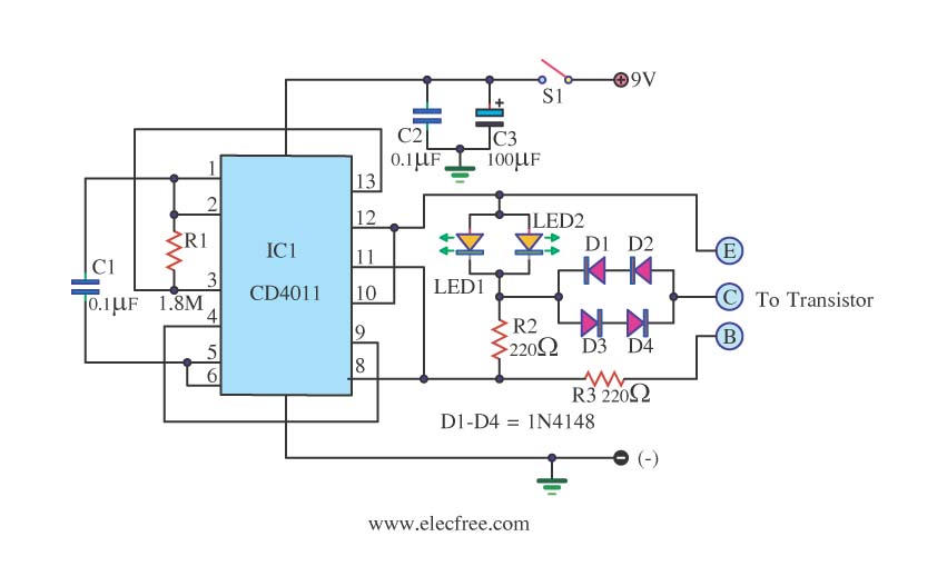
This is a transistor tester integrated into a circuit or printed circuit board (PCB). It is utilized when a project does not function correctly, allowing for the testing of electronic components. The transistor tester is a crucial tool in electronic...
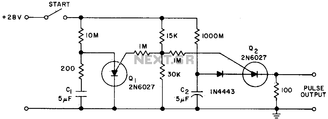
The Programmable Unijunction Transistor (PUT) serves as both a timing element and a sampling oscillator. A low leakage film capacitor is required for capacitor C2 because of the minimal current supplied to it. The Programmable Unijunction Transistor (PUT) is a...
This 555 timer circuit toggles a relay when a button is pressed. Pins 2 and 6, the threshold and trigger inputs, are held at half the supply voltage by two 10K resistors. When the output is high, the capacitor...