
Crystal Controlled Frequency Converter Circuit

The described circuit leverages the unique characteristics of dual-gate MOSFETs, particularly their ability to handle multiple inputs and provide enhanced gain control. The integration of a crystal oscillator at the second gate (G2) facilitates precise frequency control, which is critical in applications such as radio frequency (RF) mixing.
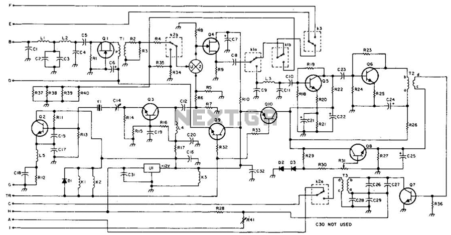
In this configuration, L3 acts as an inductor that, together with C3, forms a resonant tank circuit with X1, which is the crystal oscillator. The choice of crystal type is vital, as third-overtone crystals can significantly extend the operational frequency range, allowing the circuit to function efficiently beyond 25 MHz.
T1 and C1 are essential for ensuring that the input frequency to the converter is accurately tuned. This tuning process is crucial for maximizing the mixer’s performance and minimizing signal distortion. The output from the mixer is then processed through T2, which is designed to efficiently transfer the intermediate frequency signal to the next stage of the circuit.
Overall, this design exemplifies a sophisticated approach to RF signal processing, merging traditional techniques with modern semiconductor technology to achieve high-frequency performance in compact circuitry. The careful selection of components and their configurations is vital for optimizing the circuit's functionality and reliability in practical applications. The second gate (G2) of a MOSFET can be used to incorporate a crystal oscillator into the same stage as a frequency mixer. Although old hat with tubes, this scheme is seldom seen in dual-gate MOSFET circuitry. L3, 03, and XI form the crystal oscillator, and T2 is an IF output transformer. T1 and 01 are tuned to the converter input frequency. This circuit should be useable up to 25 MHz or so, or higher with third- overtone crystals.
Related Circuits
The TDA2030 is a monolithic integrated circuit in a Pentawat® package designed to function as a Class AB audio amplifier. It typically delivers up to 14 watts of output power (with a distortion rate of 0.5%) at 14V with...
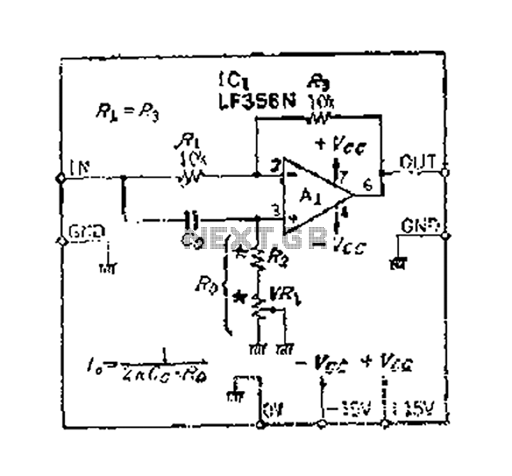
An accurate phase shift of 90 degrees can be achieved using a variable resistor (VR) and an operational amplifier (op-amp). The adjustment allows for a specific frequency to be manipulated. The phase shift can range from 180 degrees to...
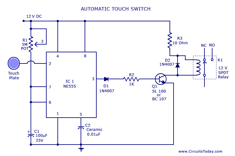
A touch switch circuit schematic utilizing a 555 integrated circuit (IC). When the touch plate is activated, a relay is switched ON for a predetermined duration, which can also be adjusted. The touch switch circuit employs a 555 timer IC...
This 49-MHz FM transmitter comprises an audio amplifier, a low-pass filter, three RF stages, and a regulated DC power supply. The output power is approximately 16 mW into a 50-ohm load. This transmitter is suitable for various 49-MHz applications,...
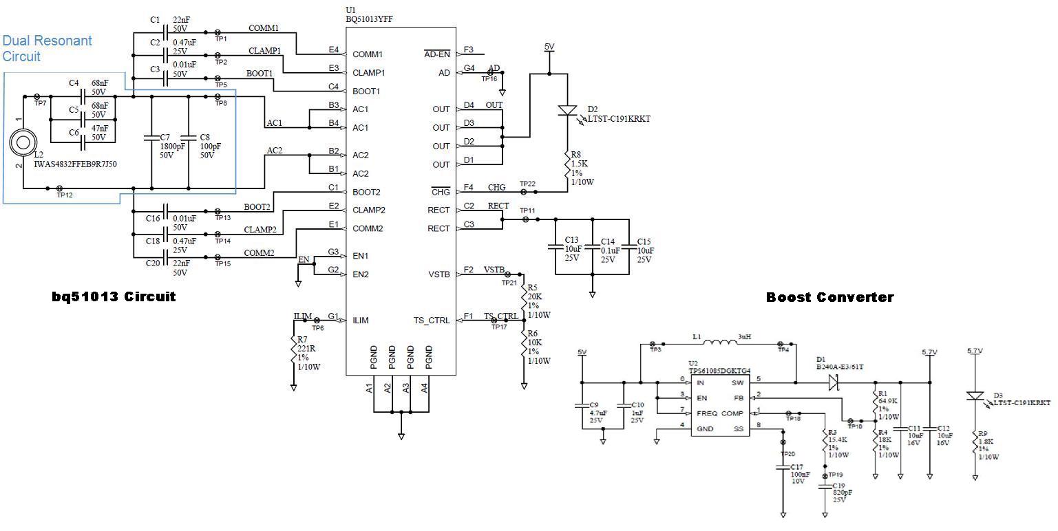
Several boards have been constructed using the bq51013 EVM receiver circuit along with a TPS61085 boost converter circuit, designed in SwitcherPRO Design Software, to elevate the voltage level to 5.7 volts. However, when a load of 580 mA, required...
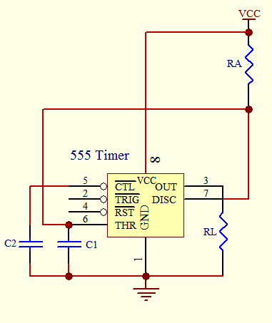
The timer circuit is utilized in various projects and is primarily categorized into two types. The first type is an analog RC circuit, where the charging of the capacitor determines the timing of the circuit. This type has a...