
Flyback Transformer Driver

The flyback driver circuit is designed to operate efficiently by leveraging a 555 timer configured in astable mode, which generates a square wave output. The frequency of oscillation can be fine-tuned through the use of adjustable trimmers, allowing for optimal performance based on the specific flyback transformer used. The totem pole output stage, consisting of the 2N3904 and 2N3906 transistors, provides sufficient drive capability to switch the IRF840 MOSFET quickly, minimizing transition losses and enhancing overall efficiency.
The choice of the IRF840 MOSFET is crucial due to its high voltage and current ratings, making it suitable for high-power applications typically encountered in flyback transformer circuits. The inclusion of a snubbing network, typically consisting of a resistor and capacitor, is essential for protecting the circuit from voltage spikes that can occur during the switching process. This network helps to absorb transient voltages, thereby extending the lifespan of the components involved.
Overall, this flyback driver circuit is versatile and can be adapted for various applications beyond television flybacks, including ignition coils and other high-voltage transformer systems. The ability to adjust frequency and duty cycle allows for experimentation with different transformer types, making this circuit a valuable resource for electronics enthusiasts and engineers alike.an efficient flyback driver for modern cylindrical rectified television flybacks. Many sites doesn`t provide circuits driving these transformers, they simply say that they are bad. I don`t agree. In fact I built this circuit. I spent a lot of time for finding resonant frequency (around 15Khz) and duty cycle. These transformers best work at around 90% duty cycle. You may notice corona breakdown at terminals and pfffff sound (as well as the ozone smell) when adjusting the off time trimmer to near 500-300 ohms. Of course it will work for other tipes of flyback as frequency and duty cycle have a large range. Frequency range can be increased using multiposition switch for other values of C3 capacitor, for example 2 nF for 80KHz-200000KHz, but didn`t found flybacks with so high resonant frequencies, in addition with higher values of c3, eg 200nF, 2uF the frequency will drop making possible the use of ignition coils, and rectified power transformers @50Hz to charge high voltage electrolitic caps at 300-400V).
Unfortunately my ignition coil died because insulation breakdown (too long drawn arcs). The 555 is wired as an astable and the capacitor is charged only through the 4, 7Kohm trimmer (notice the diode) and discharged only through the 2. 2 Kohm trimmer, making the duty cycle full adjustable. The square wave is then feed in a totem pole made up of a 2N3904 and a 2N3906, which are cheap, and easy to find.
The totem pole ensures the gate being charged and discharged very fast (approx 50nS i think). The IRF840 is a cheap (i found it for 4euros) reliable and powerful power mosfet, it has current capability of 8 A continuous and 32A pulse, 800V drain source voltage, protecting internal zener diode. There is a snubbing network to ensure that voltage spikes are kept low (unless the insulation of the transformer start to leak) protecting both transistors and 555 IC.
100 ohm is a compromise between decay time and voltage spike. 🔗 External reference
Related Circuits
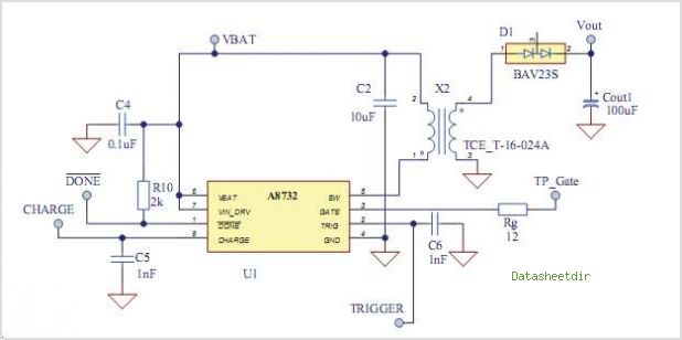
The AAT1265 evaluation board serves as a platform for testing and evaluating the AAT1265 low voltage 2MHz step-up regulator. This evaluation board illustrates the recommended size and arrangement of external components necessary to maintain output voltage regulation for up...
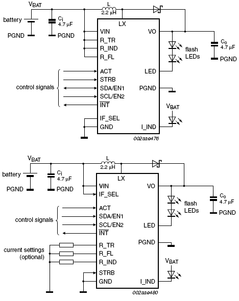
This device offers an extended battery life and operates with low power consumption. Additional features include battery and LED overload protection, seamless operation with safeguards against overtemperature, overvoltage, a timeout function, undervoltage lockout, and feedback short-circuit protection. The device is...
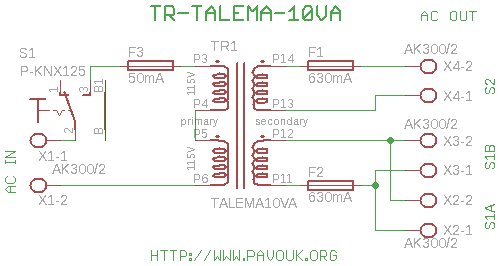
All DAC boards include a power supply section. It is sufficient to connect only a power transformer. This board is designed for a toroidal 10VA transformer manufactured by Talema, which features pins for PCB connection and exhibits minimal electromagnetic...
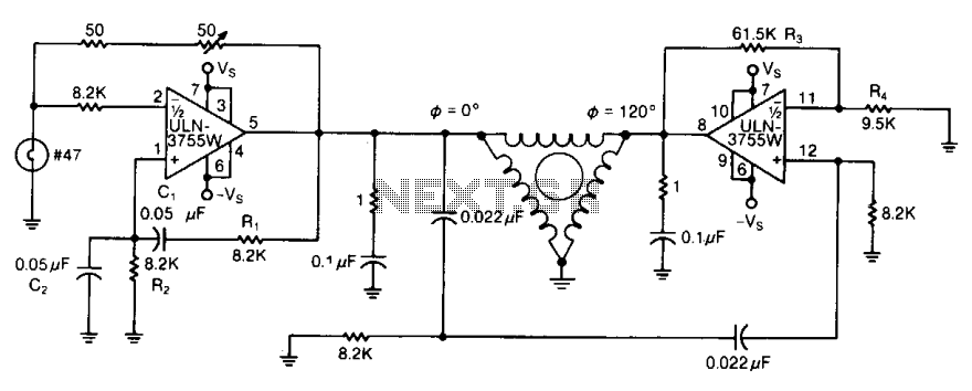
By varying either R1 or R2, the oscillator frequency can be adjusted over a narrow range. The R3/R4 ratio sets the second amplifier's gain to compensate for signal attenuation occurring in the phase shifters. The circuits can be driven...
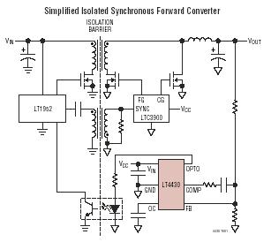
The LT4430 drives the opto-coupler that crosses the galvanic barrier in an isolated power supply. The IC contains a precision-trimmed reference, a high bandwidth error amplifier, an inverting gain of 6 stage to drive the opto-coupler, and unique overshoot...
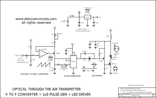
This circuit receives the signal from the amplifier and emits powerful 1μs infrared light pulses from a low-cost LED, which are frequency modulated by the audio information. The 10kHz center frequency of the pulse stream is sufficiently low, allowing...