
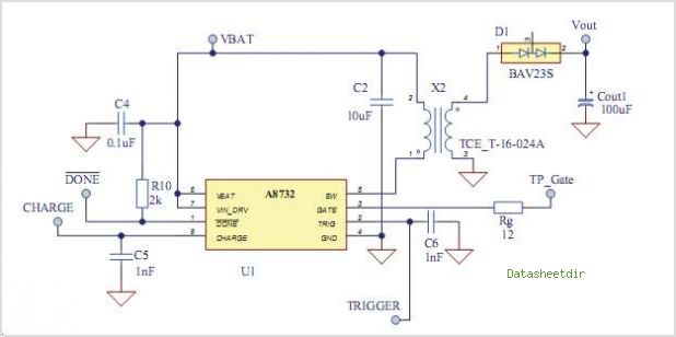
Ultra Small Mobile Phone Xenon Photoflash Capacitor Charger With IGBT Driver
The AAT1265 evaluation board is engineered to facilitate the assessment of the AAT1265 low voltage step-up converter, which operates at a frequency of 2MHz. The board's design is crucial for maintaining voltage regulation while sourcing up to 250mA of output current, making it suitable for various portable electronic applications. The external components, including inductors and capacitors, are meticulously chosen for their small footprint, ensuring that the overall design remains compact and efficient.
The layout of the evaluation board is optimized to minimize parasitic inductance and resistance, which can adversely affect performance. This optimization is particularly important in high-frequency applications where switching losses can significantly impact efficiency. The use of the SC70JW-8 package further enhances the board's space efficiency, allowing for integration into compact devices.
The input voltage range of 0.8V to VOUT enables the board to operate effectively with low-voltage power sources, such as dual AA batteries, making it versatile for battery-operated devices. The specified output voltage of 3.3V is a standard requirement for many digital circuits, ensuring compatibility with a wide range of applications.
Operational testing of the AAT1265 evaluation board involves monitoring the output voltage and current under various load conditions to verify the regulator's performance. The evaluation board also provides test points for measuring input and output voltages, as well as current monitoring, facilitating comprehensive performance analysis.
In summary, the AAT1265 evaluation board is a well-designed tool for engineers and developers looking to evaluate the performance of the AAT1265 step-up regulator in portable applications, ensuring that both design and testing processes are streamlined and efficient.The AAT1265 evaluation board provides a platform for the testing and evaluation of the AAT1265 low voltage 2MHz Step-up Regulator The evaluation board demonstrates suggested size and placement of external components to main- tain output voltage regulation for up to 250mA of output current. The external components are selected for small size to sui t portable applications while the layout has been optimized to achieve high efficiency with the SC70JW-8 package. The design operates across an input voltage range of 0. 8V to VOUT. The AAT1265 EVAL demo board provides a 3. 3V output at 250mA maximum output current for a dual AA cell input. This document provides details on the operation and testing of the AAT1265 evaluation board. AAT1265IJS Low Voltage 2MHz Step-up Converter 🔗 External reference
Related Circuits
Posts about a tutorial written by Harandi and Amirsab. The content refers to a series of instructional posts focused on a particular tutorial authored by individuals identified as Harandi and Amirsab. These posts likely encompass various topics related to electronics,...
The barrier measurement method for distance is based on assessing the strength of a bound signal. A reflection wave is captured with an acceptor transducer, which emits a sine wave signal. The amplitude of this signal varies with the...
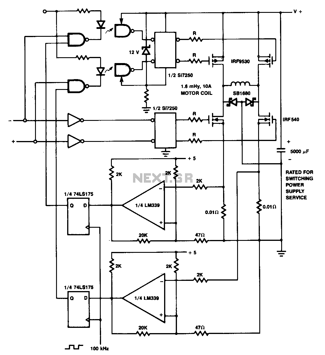
The p-channel devices are deactivated by current sensors when the coil current reaches 10 A. The operation resembles that of a switching-type power supply. Additionally, Schottky diodes and resistors are utilized for spike protection. In this circuit, p-channel MOSFETs serve...
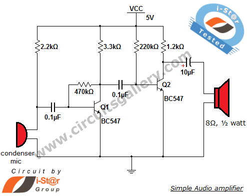
This circuit diagram is a simple and effective design for amplifying weak signals from a capacitive condenser microphone. It is suitable for sound sensing applications and various automatic robotic sensors. While a more complex audio amplifier circuit using the...
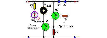
This circuit is designed to detect whether the load of a battery charger or plug-in adapter is properly connected. The load may consist of a set of batteries needing charging or any other device that operates on low DC...
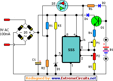
This automatic NiCd charger for 9V NiCd batteries utilizes the properties of a 555 timer and is straightforward to construct. The design allows for continuous charging of the battery without the risk of overcharging or discharging. With the specified...
Warning: include(partials/cookie-banner.php): Failed to open stream: Permission denied in /var/www/html/nextgr/view-circuit.php on line 713
Warning: include(): Failed opening 'partials/cookie-banner.php' for inclusion (include_path='.:/usr/share/php') in /var/www/html/nextgr/view-circuit.php on line 713