
FM And AM Digital IC

The described transmitter circuit is designed to operate at two distinct frequency bands, enabling the simultaneous transmission of Frequency Modulation (FM) and Amplitude Modulation (AM) signals. The FM signal operates at 100 MHz, which is within the typical range for FM broadcasting, while the AM signal operates at a lower frequency of 20 MHz, suitable for medium wave AM broadcasting.
The circuit can be divided into several key components. First, an oscillator circuit generates the carrier frequencies for both the FM and AM signals. The FM oscillator is tuned to 100 MHz, while the AM oscillator is set to 20 MHz. These oscillators may utilize crystal-controlled oscillators (CXOs) or phase-locked loops (PLLs) to ensure stability and precision in frequency generation.
Next, the modulation stages must be implemented. The FM modulator alters the frequency of the carrier wave based on the input audio signal, which can be achieved using a varactor diode or a frequency modulation IC. For the AM modulation, the amplitude of the 20 MHz carrier wave is varied in accordance with the audio input signal, typically using a transistor or an operational amplifier configured as a modulator.
The outputs of both modulation stages are combined using a mixer circuit, which allows the simultaneous transmission of both signals. Filtering techniques may be employed to prevent interference between the two frequency bands, ensuring clear transmission. A power amplifier may also be included to boost the output signals to the desired transmission levels, followed by an appropriate antenna system designed to efficiently radiate both FM and AM signals.
Overall, this transmitter circuit provides a versatile solution for broadcasting both FM and AM signals, making it suitable for various applications in radio communication and broadcasting.This is transmitters circuit that can transmit both FM and AM signal simultaneously at two different frequencies FM in 100Mhz and Am in 20 MHz. Here is the .. 🔗 External reference
Related Circuits
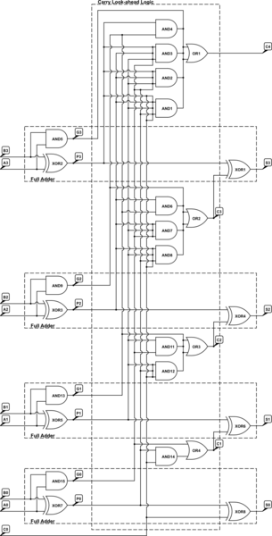
A 4-bit Carry Look Ahead Adder has 3 gate delays for all carry bits and 4 gate delays for all sum bits, whereas ripple adders have 7 and 8 gate delays, respectively. The 4-bit Carry Look Ahead Adder (CLA)...
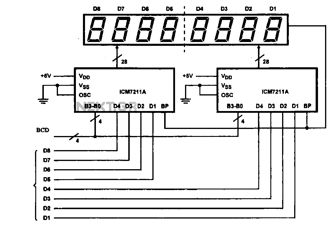
This circuit illustrates an 8-digit digital tube display driver, utilizing two ICM7211A integrated circuits. A BCD (Binary-Coded Decimal) to binary data signal is transmitted to the BO-B3 pins of the ICM7211A. The digital signals are divided into two groups...
The digital clock circuit is based on the MM5314N IC, which contains all the necessary components. The IC collaborates with six common anode displays, which can be selected in various dimensions by adapting the pins in the circuit. The...
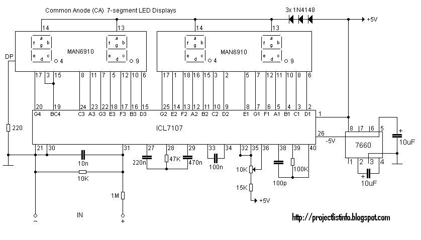
This digital voltmeter is suitable for measuring the output voltage of a DC power supply. It features a 3.5-digit LED display with a negative voltage indicator, capable of measuring DC voltages from 0 to 199.9V with a resolution of...
This circuit measures the distance covered during a walk. The hardware is housed in a compact box that can be conveniently placed in a pants pocket. The display is designed as follows: the leftmost display, D2 (the most significant...
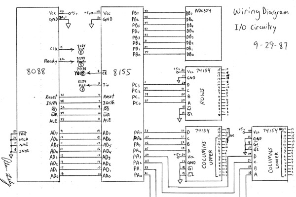
This is an early test program (assembly source code) that was stored on the erasable programmable memory chip (EEPROM). Assembler programming is just one step above programming at the binary level. The described early test program utilizes assembly language, which...