
digital logic How to calculate Gate Delays in normal Adders and Carry Look Ahead Adders

The 4-bit Carry Look Ahead Adder (CLA) is designed to improve the speed of binary addition by reducing the time required to calculate carry bits compared to traditional ripple carry adders. In a ripple carry adder, each carry bit must wait for the previous carry bit to be calculated, resulting in a cumulative delay that can significantly impact performance, especially in larger bit-width adders.
The CLA utilizes a more sophisticated approach by employing generate (G) and propagate (P) signals to determine the carry bits in parallel. The generate signal indicates whether a carry will be produced from a given bit position, while the propagate signal indicates whether a carry will be propagated to the next bit. The carry-out for each bit can be computed using the equations:
- C1 = G0 + P0 * C0
- C2 = G1 + P1 * C1
- C3 = G2 + P2 * C2
- C4 = G3 + P3 * C3
This allows for the simultaneous calculation of carry bits, which is the reason for the reduced gate delay of 3 for carry bits in a 4-bit CLA. The sum bits are calculated using the carry signals and the input bits, leading to a total of 4 gate delays for the sums.
In contrast, a ripple carry adder experiences a sequential delay, where each carry must be computed before proceeding to the next, resulting in longer delays of 7 and 8 gate delays for carry and sum bits, respectively. The efficiency of the CLA makes it ideal for high-speed arithmetic operations in digital circuits.For a 4-bit Carry Look Ahead Adder have 3 gate delays for all carry bits and 4 gate delays for all sum bits, while it is stated as 7 and 8 in case of ripple adders. How, was this calculated The image of 4 bit carry look ahead adder is shown below: 🔗 External reference
Related Circuits
There is an interest in creating an interactive LED game board or a "Stargate" DHD-type sci-fi prop, where each tile is illuminated from below by either a single white LED or an RGB combination. The goal is to make...
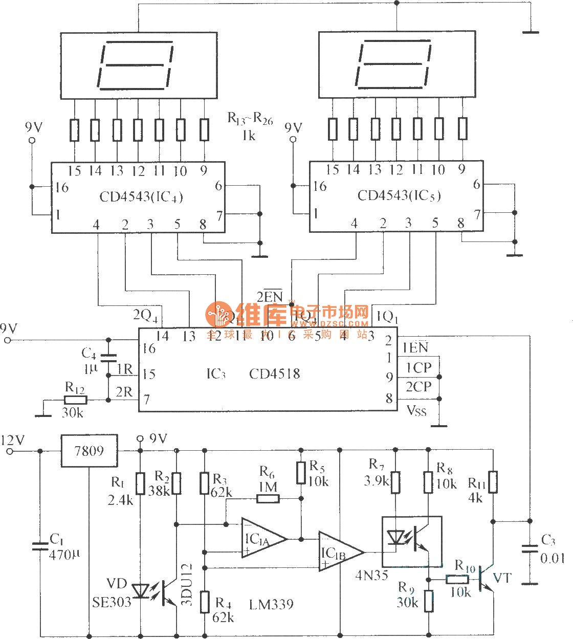
The circuit includes an optical input circuit (VD, 3DU12), a pulse forming circuit (IC1A, IC1B functioning as a voltage comparator; optical coupler; transistor switching circuit), and a counting and display circuit. The circuit architecture consists of several key components that...
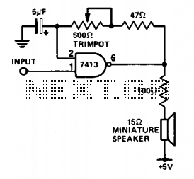
This circuit is useful for monitoring slow logic pulses as a keying monitor or digital clock alarm. The Schmitt trigger is connected as an oscillator. The trimpot controls the pitch of the output. When the input goes high, the...
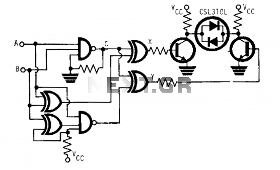
The CSL310L is a dual-color LED that incorporates a red LED and a green LED arranged back to back within a single housing. This LED can emit either red or green light depending on the polarity of the applied...
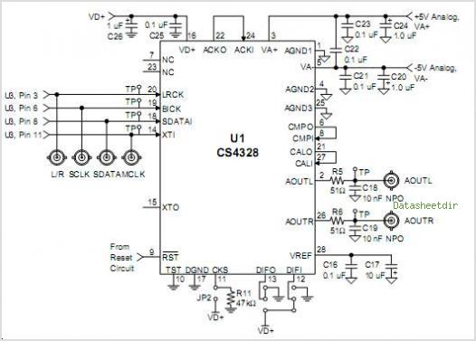
The CS4811 is a complete audio effects processing system integrated on a chip. This device features a proprietary 24-bit audio processing engine, substantial on-chip RAM, and a high-performance 24-bit audio codec. A serial control port enables the device to...
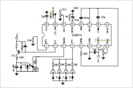
The SA9618A is designed for ALPC and signal conversion between a CD optical pickup and a decoding chip. This integrated circuit (IC) features an interconnection for a general CD optical pickup photodiode bias voltage VREF generation circuit, an RF...