
FM bug circuit

The only critical component in the FM BUG is the oscillator coil. When it is stated as critical, it refers to its effect on the frequency. Its critical nature means it must not be touched when the transmitter is in operation as this will detune the circuit completely. It is the only component that needs to be adjusted or aligned, and the winding and formation will be covered in detail. The oscillator coil is made of tinned copper wire and does not need any insulation. This is not normal practice, but since the coil is small and rigid, the turns are unable to touch each other and short out. The coil is made by winding the tinned copper wire over a medium-size Philips screwdriver. The gauge of wire, the diameter of the coil, and the spacing between turns are not extremely important and will be adjusted in the alignment stage. However, when the project is fully aligned, it must not be touched at all. The coil has 5 turns and is wound on a 3.5mm shaft. To be more specific, it has 5 loops of wire at the top, and each end terminates at the PCB. The coil must be wound in a clockwise direction to fit onto the board, and if a mistake is made, it should be rewound in the opposite direction.
Construction is straightforward as everything is mounted on the printed circuit board (PCB). The only point to watch is the height of some components. The electrolytic must be folded over so that the board will fit into the case. Positioning of the parts is not as critical as it may seem, as the final frequency is adjusted by squeezing the coil together or stretching it apart. However, it is important to keep the component leads as short as possible and the soldering neat due to the high frequencies involved. The components must be soldered firmly to the board so that they do not move when the transmitter is being carried. Even the poorest soldering will work, but a neat appearance is preferred. The soldering may not affect the resulting frequency, but poor layout of the components certainly will. All resistors must be pressed firmly against the PCB before soldering, and the two transistors must be pushed so that they are as close as possible to the board. Some BC 547 transistors may not work in the circuit; possibly due to the frequency being too high. SGS BC 547 transistors did not work at all, while the other two types, f BC 547 and Philips BC 547, worked perfectly.
All small-value capacitors are ceramic as they are not critical in value and do not need to be high stability. Care must be taken when identifying them, as it is easy to mistake a 56p for a 5p6 due to size. A 22n capacitor may be identified with 223, 22n, or .022 markings. A capacitor marked 22k will be a 22p cap and will not be suitable. The 1n capacitor may be marked 1n, .001, or 102, all of which are the same value. However, 101 or 103 is not 1n, so caution is advised; the caps may be similar in size. The rule is: do not use a capacitor unless its markings are clear and the value is certain.
The switch is mounted on the PCB with its three terminals fitted into the large holes. The final items to add to the board are the two AAA cells. These come with the kit and have been chosen for slenderness so that they can be fitted side-by-side. Soldering to the zinc case can be difficult, but roughening the surface with a file and using a large, hot soldering iron can facilitate the task. A piece of tinned copper wire should be used to join the positive of one cell to the negative of the other. At the other end, longer lengths of wire should be soldered to connect directly to the PCB, ensuring the positive terminal connects to the plus on the PCB.This is just one of the many bugging devices available on the eaves-dropping market. The range includes pen and pencil holders, trophies, framed pictures and office furniture with false bottom drawers. These products are readily sold to fledgling companies, eager to nestle into big brother's market. And for a while these bugging devices worked. Few firms knew of their existence, and even less on how to sniff them out. But that has all changed now. If a corporation suspects a leak at any level, the first thing they order is an investigation into security.
Not only personnel, but information and electronic security. Debugging has grown into big business. Most large security organisations have a section concentrating on electronic surveillance including bugging and debugging. They use scanners to detect hidden devices and can locate absolutely anything, anywhere, and on any frequency.
It was only after the firm above had commissioned a scan of the entire floor, that the cigar box was discovered. Its innocence had deceived everyone. And cost them a small fortune! Bugging of this kind is completely illegal and we don't subscribe to this type of application at all.
But the uses for our SUPER-SNOOP FM WIRELESS MICROPHONE can be harmless, helpful and a lot of fun. Our unit is both compact and very sensitive and can be used to pick up even the faintest of conversations or noises and transmit them 20 or so metres to any FM receiver. When you build the FM BUG you will see why we consider the design to be very clever. We have used only low priced components and they are all easy to obtain. No air trimmer capacitor is required as the coil is squeezed slightly to obtain the desired frequency.
This has allowed us to fit the bug into a tooth-brush case so that it can be carried around or placed on a shelf. If it is set between two books it will be hidden from view or as a supervision accessory it can be placed on a small child, etc.
The transmitted signal will over-ride the background noise and the output will be clean. If the child wanders beyond the range of the transmitter, the background noise will come up and signal that the tot is out of range. As an added bonus, you can listen to the chatterings and squabbles as the children amuse themselves in the back yard.
It is also great for picking up the first signs of a child awakening from his afternoon sleep or it can be used as an indicator from a bed-ridden patient. The great advantage of the bug is the absence of wires. And since it draws only about 5-10 milliamps, the pair of AAA cells will last for many months. The success of this FM BUG is the use of TWO transistors in the circuit. To create a good design, like this, each transistor should be required to perform only one task. In any type of transmitter, there is a minimum of two tasks. One is to amplify the signal from the microphone and the other is to provide a high frequency oscillator.
The amplified microphone signal is injected into the oscillator to modify its frequency and thus produce a FREQUENCY MODULATED oscillator. If an aerial is connected to the output of the oscillator, some of the energy will be radiated into the atmosphere.
To increase the output of our design, an RF amplifier would be needed but this gets into legal technicalities with maximum transmitting power. It may be of Interest to know that a record distance of 310 miles was achieved with a 350 micro-watt transmitter in the USA, some 15 years ago.
This equates to an astounding ONE MILLION miles per watt! In simple terms, an RF amplifier becomes a LINEAR amplifier. We have opted for sensitivity and the first transistor is employed as a pre-amplifier. This will enable you to pick up very low-level sounds and transmit them about 20 to 50 metres. The only critical component in the FM BUG is the oscillator coil. When I say critical, I am referring to its effect on the frequency. Its critical nature only means it must not be touched when the transmitter is in operation as this will detune the circuit completely. It is the only component which needs to be adjusted or aligned and we will cover its winding and formation in detail.
The oscillator coil is made out of tinned copper wire and does not need any insulation. This is not normal practice but since the coil is small and rigid, the turns are unable to touch each other and short-out. The coil is made by winding the tinned copper wire over a medium-size Philips screw-driver. The gauge of wire, the diameter of the coil and the spacing between turns is not extremely important and it will be adjusted in the alignment stage.
However when the project is fully aligned, it must not be touched at all. Don't be over-worried at this stage. Just follow the size and shape as shown in the diagram and everything will come out right in the end. The coil has 5 turns and is wound on a 3.5mm shaft. To be more specific, it has 5 loops of wire at the top and each end terminates at the PC board. The coil must be wound in a clock-wise direction to fit onto the board and if you make a mistake, rewind the coil in the opposite direction.
Construction is quite straight-forward as everything is mounted on the printed circuit board. The only point to watch is the height of some of the components. The electrolytic must be folded over so that the board will fit into the case. Positioning of the parts is not as critical as you think as the final frequency is adjusted by squeezing the coil together or stretching it apart. However it is important to keep the component leads as short as possible and the soldering neat due to the high frequencies involved.
The components must be soldered firmly to the board so that they do not move when the transmitter is being carried. Even the poorest of soldering will work but who wants to see poor soldering on a project? The soldering may not affect the resulting frequency but poor layout of the components certainly will.
All the resistors must be pressed firmly against the PC board before soldering and the two transistors must be pushed so that they are as closes as possible to the board. Some BC 547 transistors will not work in the circuit. Maybe the frequency is too high. SGS BC 547 transistors did not work at all. The other two types: f BC 547 and Philips BC 547 worked perfectly. All the small-value capacitors are ceramic as they are not critical in value and do not need to be high stability.
But you must be careful when identifying them. It would be a very simple mistake to buy a 56p instead of 5p6 because there is no difference in the size. 22n may be identified with 223 or 22n or .022. A capacitor marked 22k will be a 22p cap and will not be suitable. The 1n capacitor may be marked 1n or .001 or 102. These are all the same value. The value 101 or 103 is NOT 1n so be careful, the caps may be about the same size. The rule is: don't use a capacitor unless its markings are clear and you are sure of the value. The switch is mounted on the PC board with its three terminals fitted into the large holes. The final items to add to the board are the two AAA cells. These come with the kit and we have chosen them for slenderness so that they can be fitted side-by-side.
It is very difficult to solder to the zinc case but if you roughen the surface with a file and use a large, HOT, soldering iron, the job can be done very quickly. Use a piece of tinned copper wire to join the positive of one to the negative of the other. At the other end, solder longer lengths of wire so that they can be connected directly to the PC board.
Make sure the positive terminal connects to the plus on the PC board. 🔗 External reference
Related Circuits

In this circuit, a square wave is filtered using a high-order low-pass filter designed to eliminate most harmonics of the waveform at a -3 dB frequency. Consequently, the output of the filter is a fundamental sine wave. This technique...
A simple 9 Volt, 2 amp power supply utilizing a single integrated circuit (IC) regulator. This circuit is straightforward, as the regulator handles the majority of the work. The component used is the 7809 voltage regulator. The circuit consists primarily...
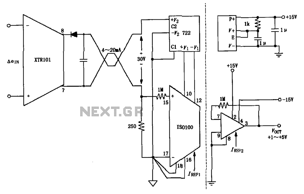
The circuit combines the XTR101 with the ISO100 isolation amplifier to transform a 4-20 mA current signal into a voltage output ranging from +1V to +5V while providing power supply isolation. It features excellent anti-jamming capabilities, making it suitable...
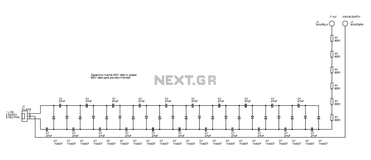
A basic mains driven Cockroft ladder high voltage generator is shown in the schematic. This is functionally the same as a project in Electronics Today International many years ago. The peak mains voltage of 340V appears across each capacitor...
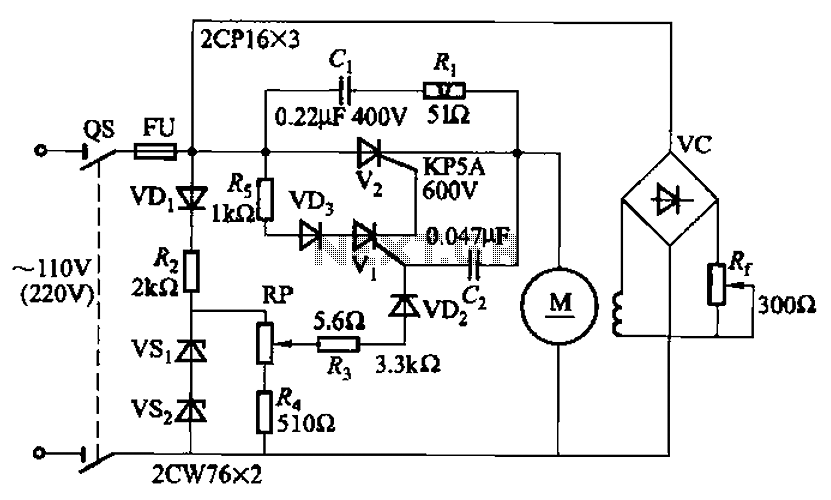
A 100W resistance-triggered motor control circuit designed for arc welding machines. It features an adjustment potentiometer (Rr) that can modify the DC motor excitation current. Additionally, a regulator (RP) is included to adjust the DC motor armature voltage, enabling...
The FM302E-I-type FM transmitter exciter is manufactured by NEC Corporation, Japan, and features a 1210 motherboard. It utilizes direct frequency modulation of the carrier signal, employing phase-locked frequency stabilization and frequency synthesis techniques. The front power amplifier is based...