
FM Bug Transmitter Mint Box Circuit

The FM transmitter circuit operates by converting audio signals into radio frequency signals, making it possible to transmit sound wirelessly. The electret microphone serves as the initial input device, capturing sound waves and converting them into electrical signals. The 22k resistor connected to the microphone ensures that the input signal is at an appropriate level for processing.
The amplifier circuit typically comprises a transistor configuration that boosts the input audio signal. This amplification process is crucial because it enhances the signal strength, allowing it to be effectively transmitted over greater distances. The choice of components in the amplifier, including the transistor type and any associated resistors or capacitors, influences the gain and bandwidth of the circuit.
Following amplification, the circuit utilizes a second BC547 transistor to function as an oscillator. This transistor generates a carrier frequency, which is essential for FM transmission. The mixing process occurs when the audio signal is combined with the generated carrier frequency, resulting in frequency modulation. This modulation alters the frequency of the carrier wave in accordance with the amplitude of the audio signal, encoding the audio information onto the radio wave.
The antenna at the end of the circuit facilitates the transmission of the modulated signal into the air, where it can be received by compatible FM receivers. The design of the antenna, including its length and type, can significantly affect the transmission range and quality of the signal.
In summary, the FM transmitter circuit is a sophisticated assembly of components that work together to enable wireless audio transmission. Each part, from the electret microphone to the antenna, plays a pivotal role in ensuring effective modulation and transmission of sound. The details of the circuit's operation and the theory behind frequency modulation will be elaborated upon in the following sections.Here is the circuit for the FM Bug. In total there are 18 core components that are needed for the fm transmitter to work properly. The far left side has the electret microphone and then things move electrically to the right until they hit the antenna. Don`t let this microphone fool you, it`s extremely sensitive albeit a bit clunky and big. You co uld shop around for a smaller microphone I`m sure but for this project, a standard electret microphone does the trick. The input is pulled high with a 22k resistor and passed to the amplifier circuit. The amplifier`s job in this circuit is to take the audio input and beef up the voltage/current so that when it gets transmitted it travels further.
More amplification means more higher fm transmitting power and longer range. The last portion of the circuit with the 2nd BC547 is where the oscillator for the FM frequency is generated and mixed with the audio signal inorder to form the frequency modulation used for FM radio. Don`t worry, if all this is described a bit too quickly, the theory will be desribed more indepth in the next section.
🔗 External reference
Related Circuits
This circuit offers an advantage over traditional continuity testing devices, which typically utilize a multimeter to assess circuit continuity. Multimeters are not suitable for testing high impedance or resistance circuits, such as transformers, capacitors, and high-value resistors. This circuit...
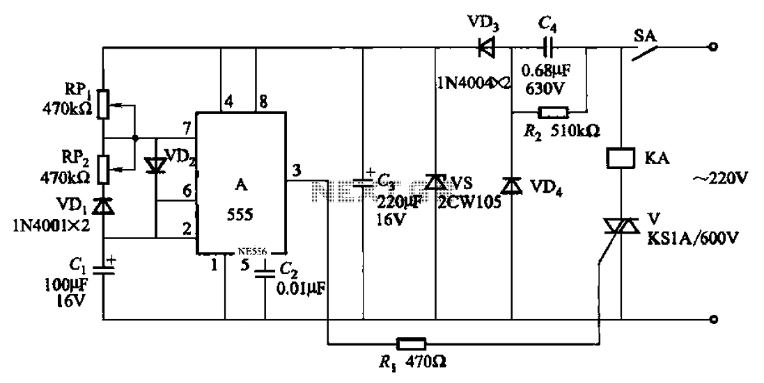
An automatic cycle switch circuit utilizing a 555 integrated circuit (IC) as the control element. It incorporates a capacitive step-down circuit and employs a bidirectional thyristor to control relays or loads with specific on and off timing. The circuit...
The only drawback of a single operational amplifier (op-amp) stage is that it inverts the signal, necessitating an additional inverting buffer to restore the original phase if absolute phase is a concern. Various schematics exist for both configurations, but...
ETl3X220 is a cost-effective single-chip transmitter that operates via RF communication. It supports up to 10 channels and is ideal for applications such as wireless mice, keyboards, and other communication devices. The main technical features include: - Analog FM...
The LM1036 is a DC-controlled circuit designed for adjusting bass, treble, balance, and volume in stereo applications, particularly in car radios, televisions, and audio systems. An additional control input enables the implementation of loudness enhancement. Four control inputs facilitate...
The TDA7294 amplifier module is a monolithic integrated circuit designed for use as a Class AB audio amplifier in high-fidelity applications. It features a wide voltage range and output current capability, allowing it to deliver high power to both...