
FM by a timer ME555 circuit

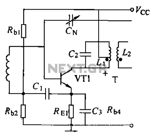
The NE555 timer is a versatile integrated circuit used for generating precise timing and oscillation. In this application, it operates as a multivibrator, wherein the charging current influences the output frequency. The circuit configuration allows for frequency modulation by altering the charging time, which is directly influenced by the resistors R1 and RRP1.
The current mirror circuit, composed of transistors VT1 and VT2, plays a crucial role in maintaining a consistent charging current. This is essential for stabilizing the oscillation frequency of the NE555 timer. The current mirror ensures that the current flowing through R1 and RRP1 is mirrored accurately, allowing for predictable changes in frequency modulation based on the input signal.
The low-frequency modulation signal applied to the bias current IB allows for dynamic adjustments to the output frequency of the NE555. This modulation can enable various applications, such as tone generation or signal processing, where frequency variability is necessary. The inclusion of a current Miller circuit in the tube configuration further enhances the circuit's ability to manage and utilize the current effectively, providing additional control over the modulation process.
Overall, this circuit design exemplifies the integration of a NE555 timer with a current mirror and modulation capabilities, showcasing its applicability in electronic signal generation and manipulation.The figure is composed by a NE555 and other withered frequency circuit by changing the self-excited multivibrator NE555 charging current to frequency modulation. The circuit is VT1 and VT2 constitute a current mirror circuit, the charging current can be generated in the charging circuit, the current size is determined by R1 and RRP1. Low frequency modulation signal superimposed to the bias current IB after the oscillation frequency changes. Try to use the current Miller circuit on the tube.
Related Circuits

When the preset is set to its maximum, the LED flashes at a rate of approximately once every half second. This rate can be increased by raising the capacitor value from 10µF to a higher value. For instance, if...
A wide range auto turn OFF timer covering 1 minute to 20 hours in three ranges with S1. As soon as power is applied to the circuit, the IC1 [555] starts to oscillate and feeds clock pulses to the...
This can be a thin strand of wire, like one of the copper "hairs" from a section of lamp cord, which is wired to the altimeter by terminals somewhere on the rocket body and anchored to the launch stand...
Over 1400 top electronics projects and electronic circuits with photos, datasheets, and easy-to-read schematics, along with explanations of how they work and how to build them. The collection comprises a vast array of electronics projects suitable for enthusiasts and professionals...
A common intermediate frequency amplifier circuit is presented, along with its components and parameters. The reference values for the components are as follows: 1) Transistors: VT1 to 3DG19, Vcc = 6V. 2) Resistance values: R1 = 50 kΩ, R2...
As shown in figure 14-17, this circuit consists of the input circuit, the line frequency synchronization generator, the sample-and-hold circuit, the voltage control delay generator, and the RF modulator. The input circuit includes the input attenuator RP1 and the...