
Simple Crystal Tester

The described XTal (crystal) tester circuit is designed to evaluate the functionality of quartz crystals within the frequency range of 100 kHz to 30 MHz. The circuit primarily consists of an oscillator formed by the transistor T1 and the crystal under test. This oscillator circuit is crucial for determining the operational integrity of the crystal.
Capacitors C1 and C2 serve as part of a voltage divider network, which is essential for stabilizing the oscillation frequency and providing the necessary biasing for the transistor. The output from the oscillator is then processed through a rectification stage formed by capacitors C3 and C4 and diodes D1 and D2. This rectification converts the AC signal generated by the oscillator into a DC voltage, which is required to drive the subsequent components of the circuit.
Transistor T2 acts as a switching element that is activated by the rectified voltage. When the crystal is functional, the output voltage from the rectification stage will be sufficient to turn on T2, which in turn powers the LED indicator. The illumination of the LED serves as a visual confirmation that the crystal is operational and within the specified frequency range.
Overall, this circuit provides a straightforward and effective means of testing quartz crystals, ensuring that they are functioning correctly before being deployed in more complex electronic applications. The design is compact and can be easily assembled on a breadboard or PCB for practical use.This is a simple XTal tester circuit. T1 and XTal have formed an oscillator. C1 and C2 are voltage divider for oscillator. if the XTal is safe, the oscillator will work well and its output voltage will be rectified by C3, C4, D1 and D2, then T2 will run and LED will light. The circuit is suitable to test 100KHz - 30MHz Xtal. 🔗 External reference
Related Circuits
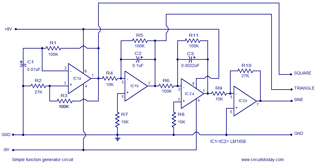
A simple function generator circuit utilizing the LM1458 is presented here. The LM1458 is a dual general-purpose operational amplifier. The two op-amps within the LM1458 share a common bias network and power supply line, yet operate independently. The function generator...
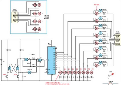
This circuit was developed to create a simple network tester that can be operated by a single individual. Commercial units typically require a second person to monitor the remote LEDs, as the transmitters lack the ability to continuously cycle...
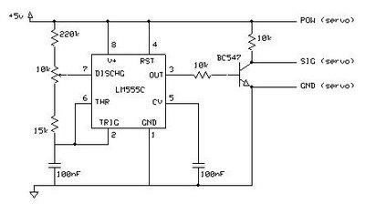
This circuit enables the testing of a servo motor. The angle of the servo can be adjusted using a 10k potentiometer. It is possible that not all positions can be achieved with this circuit; experimenting with different resistors may...
These circuits provide overvoltage protection in the event of a voltage regulator failure or the application of an external voltage. They are intended for use with a power supply that incorporates some form of short circuit protection, such as...
Do not let its extreme simplicity deceive you — this device is useful! Many have been made over the years, and some have even been given away as gifts. Yes, multimeter... A multimeter is an essential instrument in electronics, used...
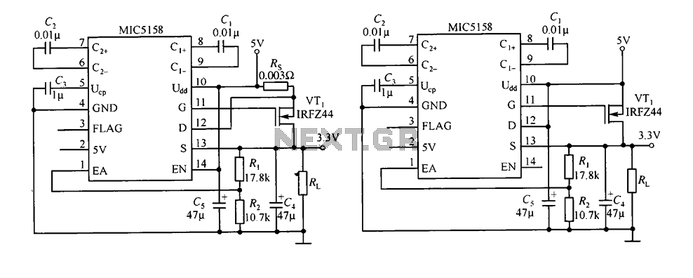
The circuit consists of peripheral components for the MIC5158, a linear regulator that converts a 5V input into a 3.3V output with a maximum current of 10A. When the input voltage (Ui) is 5V, an N-channel MOSFET, specifically the...