
keyboard circuit

The AT Keyboard Interface is a standard communication protocol used primarily in personal computers to facilitate interaction between the keyboard and the system. It operates using a serial communication method, allowing the keyboard to send keystroke information to the computer. The protocol is characterized by a simple command structure, where each key press generates a unique scan code that is transmitted to the microcontroller.
The 68HC705J1A microcontroller, a member of the Motorola 68HC05 family, is well-suited for this application due to its built-in features that support keyboard interfacing. It contains a programmable input/output port that can be configured to receive data from the keyboard. The microcontroller processes the incoming scan codes and converts them into ASCII characters, which can be utilized by software applications running on the host system.
In the implementation of a Keyboard to ASCII decoder, the microcontroller is programmed to recognize specific scan codes corresponding to each key on the keyboard. Upon receiving a scan code, the microcontroller checks its internal lookup table, which maps scan codes to their respective ASCII values. The decoded ASCII character can then be sent to the output port for further processing or display.
The schematic for this system typically includes the microcontroller connected to the keyboard via a serial line, pull-up resistors for signal integrity, and possibly a debounce circuit to ensure clean signal transitions when keys are pressed. The design may also incorporate power supply filtering to stabilize the operation of the microcontroller and the keyboard interface.
Overall, the AT Keyboard Interface and the corresponding decoding process enable effective user input management in various electronic systems, demonstrating the integration of hardware and software in embedded applications.Details the AT Keyboard Interface and AT Keyboard Protocols. Includes an example Keyboard to ASCII decoder using a 68HC705J1A MCU.. 🔗 External reference
Related Circuits
The MAX732/733 is a DC-DC current PWM step-up regulator. The MAX732 has an output voltage of +12V with a maximum output current of 200mA and an output voltage range of +4.0V to +9.3V. The MAX733 features an output voltage...
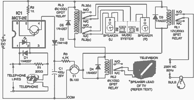
Very often when enjoying music or watching TV at high audio level, we may not be able to hear a telephone ring and thus miss an important incoming phone call. To overcome this situation, the circuit presented here can...
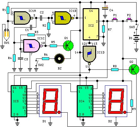
This circuit measures the distance covered during a walk. The hardware is housed in a compact box that can be conveniently placed in a pants pocket. The display is designed as follows: the leftmost display, D2 (the most significant...
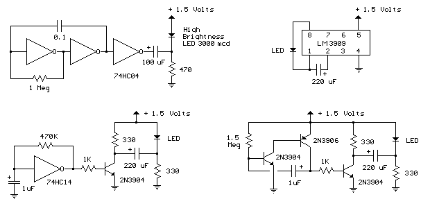
The LED flasher circuits below operate on a single 1.5 volt battery. The circuit on the upper right uses the popular LM3909 LED flasher IC and requires only a timing capacitor and LED. The top left circuit, designed by...
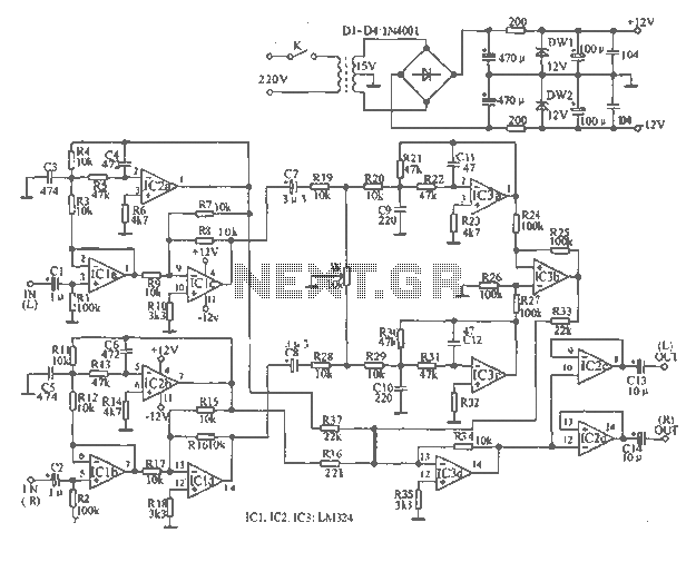
The tape output circuit processes the left and right channel signals through a first buffer amplifier. The output signal is split into two paths: one route directly connects to an amplifier for amplification, while the other route passes through...
This article offers a circuit diagram and a discussion on CMOS logic and IC layout for creating a set of attention-getting LED running lights. It details a simple sequential LED flasher or light chaser that can be built, including...