
Isolated RS422 Interface Circuit

The RS422 interface is a standard for serial communication that allows for long-distance data transmission with reduced noise interference. It is commonly used in applications requiring reliable communication over distances of up to 4000 feet at data rates of up to 10 Mbps. The circuit typically includes differential signaling, which enhances noise immunity and allows for multiple devices to communicate over a single pair of wires.
In the described circuit, the connector K1 serves as the interface point between the RS422 transceiver and the PC's serial port. The DTR (Data Terminal Ready) and RTS (Request to Send) lines are utilized to provide the necessary power for the RS422 circuitry. The RTS line supplies the positive voltage, while the negative voltage is generated through a separate circuit element, ensuring that the RS422 transceiver operates within its specified voltage range.
The RS422 transceiver itself converts the single-ended signals from the PC's serial port into differential signals suitable for RS422 communication. This process involves the use of a driver and receiver pair, which are responsible for transmitting and receiving data over twisted pair cabling. The use of twisted pair cables minimizes electromagnetic interference, further enhancing the reliability of the communication.
Proper termination and biasing of the RS422 lines are essential to maintain signal integrity, especially in longer cable runs. Termination resistors are often placed at the ends of the communication line to prevent signal reflections, while biasing resistors can help maintain the idle state of the communication line.
Overall, the RS422 interface design facilitates robust and effective data transmission, making it a preferred choice for industrial and commercial applications that require reliable serial communication. The circuit's simplicity and effectiveness in utilizing existing power lines for operation further enhance its practicality in various setups.Here s a design of the circuit diagram of RS422 interface. Connector K1 is linked to the serial port of the PC, power to the PC side of the circuit is derived from the signal lines DTR and RTS. Positive supply is derived from RTS and negative supply.. 🔗 External reference
Related Circuits

The circuit illustrated in Figure 4 is an AC timing circuit designed to operate for 4 hours. It utilizes the BH4024, a 7-stage serial binary counter/divider, in conjunction with a 555 timer circuit. The circuit is activated by a...
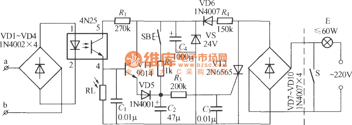
The diagram illustrates an automatic lighting control circuit activated by a telephone. At night, when the telephone rings or the user picks up the receiver, the light turns on. If the telephone stops ringing (when no one is listening)...

This circuit utilizes a Power Battery Terminal (PBT) to facilitate simple relay output and auxiliary power connections. An LED on each channel serves to indicate the status of the relay. Berg pins are provided for connecting power and trigger...
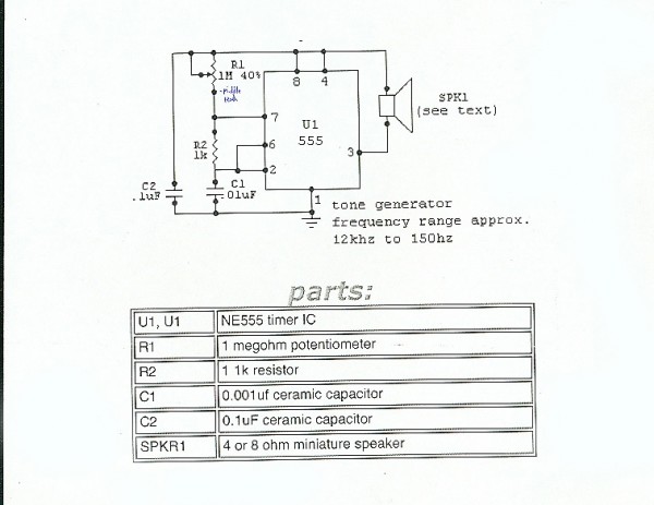
This precise one-pulse-per-second clock is constructed using a few common components and is powered by a 50 or 60 Hertz mains supply without any direct connection to it. A beep or metronome-like click, along with a visible flash, indicates...
To prevent soldering errors, students were instructed to place all their resistors on the board first. Once their placements were verified, they could proceed with soldering. Capacitors were next, followed by LEDs and other components. The middle school class...
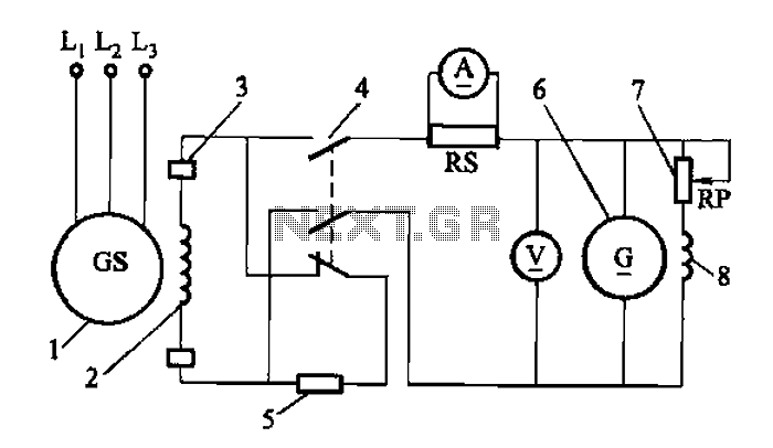
Adjust the exciter field rheostat RP to change the exciter output voltage, which in turn adjusts the generator excitation current, allowing for modifications to the generator output voltage for various purposes. The exciter field rheostat (RP) is a critical...