
fm radio circuit

The FM radio receiver circuit based on the TDA7000 IC is designed for simplicity and efficiency in capturing FM signals within the 88 to 108 MHz frequency range. The TDA7000 integrates the essential components required for an FM receiver, which significantly reduces the complexity of the circuit. The active RC filter is a critical component, consisting of an inductor that helps in tuning the desired frequency while minimizing noise and distortion in the received signal.
The circuit's output is mono, making it suitable for driving high-impedance headphones directly. For applications requiring higher power output, the mono signal can be fed into a power amplifier, allowing for a more robust audio experience. The design's simplicity is particularly advantageous for hobbyists and engineers looking to create a basic FM receiver without extensive knowledge of RF circuit design.
With the obsolescence of the TDA7000, users are encouraged to explore alternative ICs such as the TDA7010T and TDA7021T, which provide similar functionalities. The TDA7010T is particularly beneficial for applications where space is a constraint due to its surface mount design. In contrast, the TDA7021T offers the added feature of stereo sound, appealing to users seeking enhanced audio quality. When considering these alternatives, it is essential to consult the respective datasheets to ensure compatibility and proper circuit implementation, as the pin configurations and electrical characteristics may differ from the original TDA7000.
Overall, this FM radio receiver circuit serves as an excellent starting point for those interested in exploring radio frequency technology, providing a practical application of integrated circuit design in consumer electronics.This extremely simple FM radio receiver circuit is made possible by the special purpose TDA7000 IC. It integrates nearly all the functions necessary to build an FM receiver needing only a few external capacitors and a tuning circuit. Using a simple active RC filter made of only a single inductor, a few resistors and a varicap, this FM receiver wil
l pick up broadcast radio between about 88 and 108 MHz. The mono output signal can then be used to drive a set of high impedance headphones, or feed a power amplifier. Unfortunately, the TDA7000 went obsolete a few years ago. The original version is made by Signetics (now Philips) and is getting a bit hard to find these days.
There are, however, other options. Philips makes the TDA7010T which is a surface mount version. The TDA7021T is also available which includes stereo capability. They are electrically similar but are only 16 pin chips so you`ll need to compare the datasheets to build the circuit. 🔗 External reference
Related Circuits
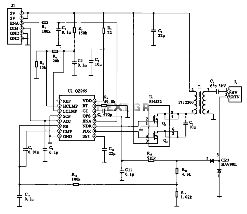
A typical liquid crystal display inverter circuit (OZ965) is primarily controlled by the OZ965 chip. It includes a driving field effect transistor (U2), a step-up transformer, the backlight socket, and associated circuitry. A 5V DC voltage is provided by...
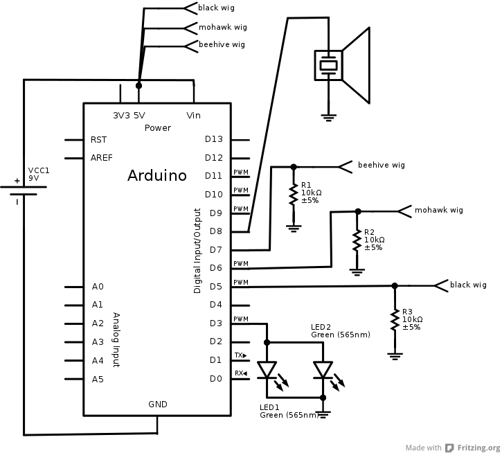
The interaction design for the singing pig was to have a different song start playing when a different wig is placed on the pig. The pig needed to stand by itself without being connected to anything else, and the...
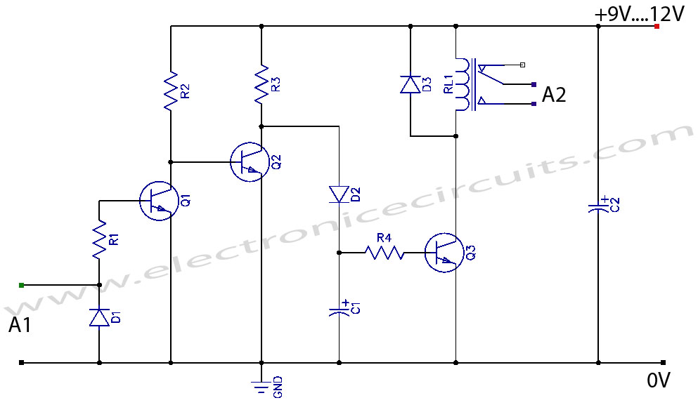
VCR Camera Video Detector Switch Controller Circuit. This video detector switch controller circuit utilizes the video output from a VCR or camera to... This circuit functions as a video detector switch controller, designed to manage the video output from a...
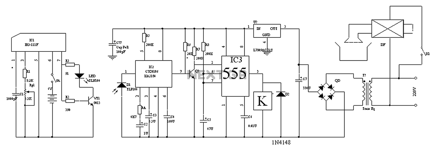
The circuit diagram for the automatic control of drinking fountains is presented below. The automatic control circuit for drinking fountains typically employs a combination of sensors and control elements to manage the operation of the fountain efficiently. The main components...
With this circuit mounted in or near every phone in the house, it will allow users to know if the phone is being used and not to pick up the phone. When a phone is taken off hook, the...
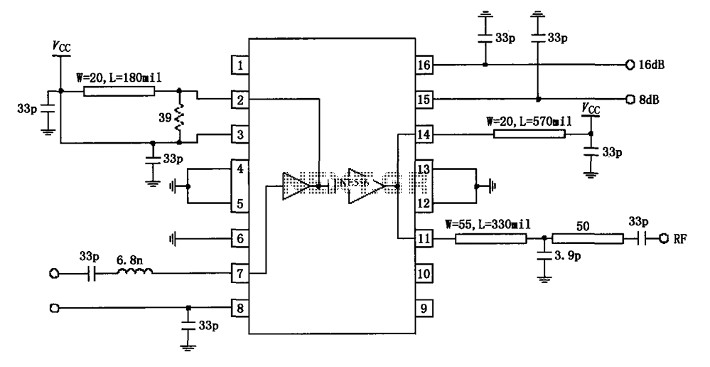
The circuit diagram illustrates the application of a 915MHz RF2155 power amplifier. The radio frequency (RF) signal enters through pin 7, where it is processed by a preamplifier. The output from the preamplifier is further amplified by the power...