
FM Radio Receiver Circuit for Battery Supply

The TDA7088T is a versatile integrated circuit that facilitates the design of compact and efficient radio receiver systems. Its architecture allows for the implementation of a Frequency-Locked Loop (FLL), which is crucial for maintaining stable frequency tuning and minimizing drift. The use of an Intermediate Frequency (IF) of around 70 kHz is standard in many radio applications, as it strikes a balance between selectivity and sensitivity.
The circuit design emphasizes the importance of using active RC filters, which enhance selectivity by allowing only the desired frequency range to pass while attenuating unwanted signals. This is particularly beneficial in environments with multiple signal sources, as it helps to reduce interference and improve overall audio clarity.
Furthermore, the mute circuit integrated within the design plays a vital role in enhancing the user experience by eliminating background noise during periods of weak signal reception. This feature ensures that only clear audio signals are amplified, thus providing a more enjoyable listening experience.
The choice of the TDA7088T is driven by its ability to operate effectively with a minimal number of external components, making it an ideal solution for portable applications where space and cost are critical factors. The design can be easily adapted for various radio frequency bands, allowing for flexibility in application while maintaining performance standards. Overall, this schematic serves as a foundation for developing efficient and reliable radio receiver circuits suitable for consumer electronics.This is a schematic for radio receiver circuit. This circuit is based on the TDA7088T that can be used in mono portable and pocket radios. This is a bipolar integrated circuit. This is the figure of the circuit; When a minimum of peripheral components (of small dimensions and low cost) is important, we can use TDA7088T. Frequency-locked -loop (FLL ) system with an Intermediate Frequency (IF) of about 70 KHz is built on this circuit. By active RC-filters, selectivity is achieved. De-tuning related to the IF and the mute circuit is suppress too week input signals. [Schematic circuit source: NXP Semiconductor Application Notes] Disclaimer All files are found using legitimate search engine techniques. This site does not and will not condone hacking into sites to create the links it list. We will and do assume that all links found on the search engines we use are obtained in a legal manner and the webmasters are aware of the links listed on the search engines.
If you find a URL that belongs to you, and you did not realize that it was "open to the public", please use the report button to notify the blogmaster of your request to remove it or it will remove within 24 hours. This is not an invitation for webblog haters to spam with requests to remove content they feel that is objectionable and or unacceptable.
Proof of URL ownership is required. NOTICE: This Blog Has Already Been Reviewed And Accepted By Blogger. com 🔗 External reference
Related Circuits
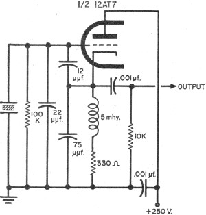
To update the fundamental oscillator circuits, simply replace the transistors with tubes. Alternatively, if one owns a vintage vacuum tube radio, it may be of interest to learn about historical practices. In general, the foundational principles of electronic circuits...
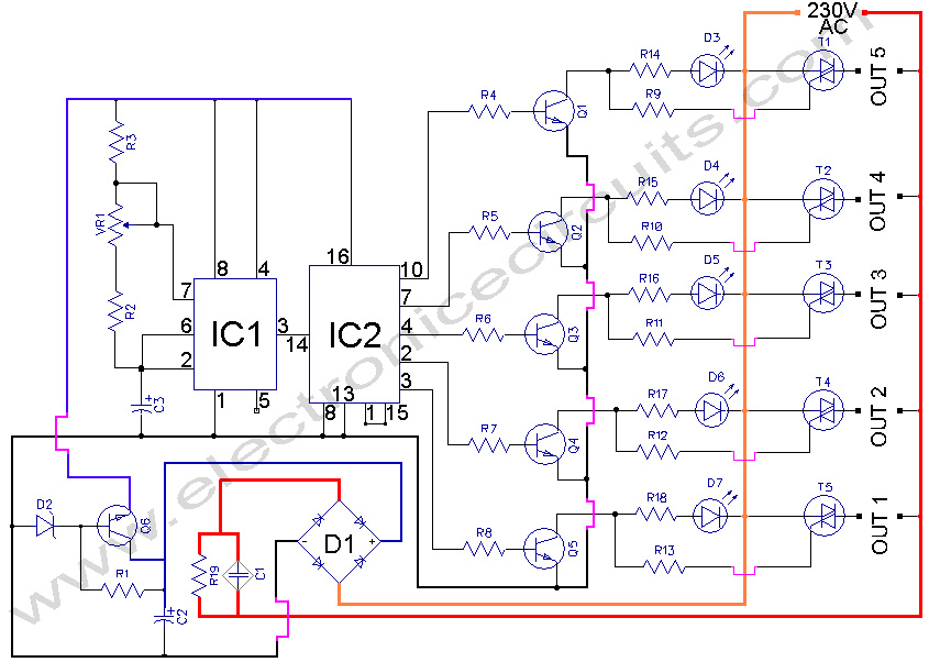
5 WAY AC FLASHER. These types of circuits are commonly used in various ceremonies such as the Wesak festival, Christmas, and weddings. This 5 WAY AC FLASHER circuit. The 5 Way AC Flasher circuit is designed to produce a sequential...
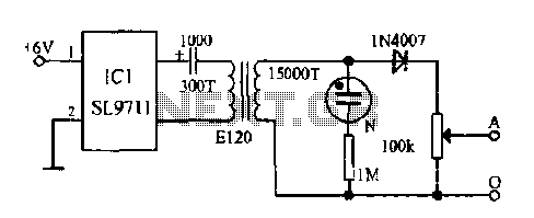
The electronic frostbite treatment instrument ASIC SL9711 consists of an oscillation circuit, a power amplifier, and a controller. It generates a sine wave at frequencies of 100 Hz and 3 Hz, followed by a step-up transformer with potentiometer adjustment...
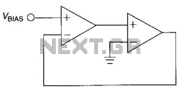
The output frequency of this simple, low-cost active voltage-controlled oscillator circuit is based on the inherent frequency-dependent characteristics of an operational amplifier. The oscillator circuit utilizes a TL082 op-amp. Upon application of power, the circuit generates a sinusoidal wave....
This circuit serves as a decorative element or indicator, featuring adjustable flashing or dancing speeds of LEDs and the ability to create various light patterns. It consists of two astable multivibrators: one formed by transistors T1 and T2, and...

To determine whether it is freezing, it is necessary to measure the temperature accurately using a reliable temperature sensor. The LM35CZ, which operates between -40 to 110 °C, has been chosen for this purpose. This sensor generates an output...