
FM stereo multiplex generator

The circuit design focuses on enhancing audio fidelity by utilizing discrete transistors instead of integrated operational amplifiers (op-amps). This shift addresses the common issue of distortion that arises when multiple op-amps are cascaded, particularly noticeable during the reproduction of sibilant sounds, such as "ess" sounds. The implementation of discrete transistor amplification stages is intended to yield a cleaner audio signal by minimizing distortion levels, thereby improving overall sound quality.
The circuit incorporates LC (inductor-capacitor) filters, which are crucial for shaping the frequency response and eliminating unwanted noise. These filters can be designed to target specific frequency ranges, ensuring that the audio output remains clear and free from artifacts introduced by previous designs.
To facilitate the alignment of the stereo modulator, a Stereo Test Tone Generator is recommended as a preliminary step. This generator is capable of producing various waveform combinations essential for calibrating the circuit. By using standard test equipment, equivalent waveforms can also be generated, providing flexibility in the testing process.
In summary, this circuit design represents a significant advancement over its predecessors by focusing on discrete components and filter design to achieve superior audio performance. The integration of a test tone generator further aids in the precise adjustment and alignment of the stereo modulator, ensuring optimal operation and sound reproduction.The design philosophy for this circuit was centered on replacing all of the op-amp circuitry found in the earlier circuits with discrete transistors and LC filters. The previous circuits had many (high quality) op-amps in series, this resulted in audible distortion, especially on "ess" sounds.
The discrete transistor amplification stages in this design produce an audio signal with much lower levels of distortion. To make alignment of the stereo modulator easy, first build this Stereo Test Tone Generator, or generate equivalent waveforms with standard test equipment. The circuit produces a number of waveform combinations that are necessary for adjusting this circui 🔗 External reference
Related Circuits
This circuit generates sine, square, and triangle waves ranging from 0.1 Hz to 1 MHz. It includes a counter that measures the frequency of the function generator or an external signal with a peak-to-peak voltage of a few volts,...
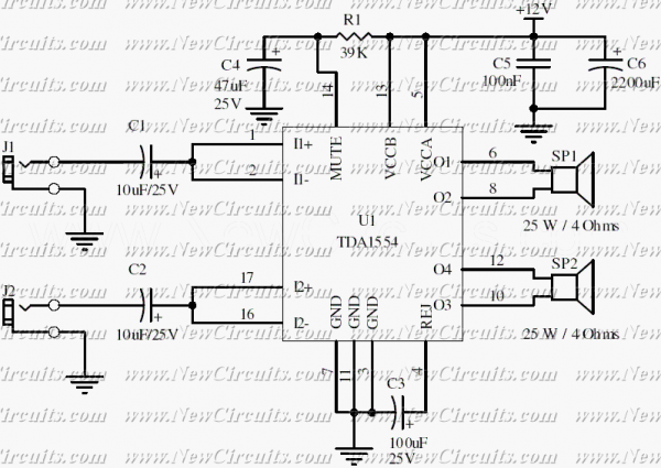
Very simple and useful circuit for amplify the stereo signals. The circuit dissipates roughly 28 watts of heat, so a good heatsink is necessary. The chip should run cool enough to touch with the proper heatsink installed. The circuit...
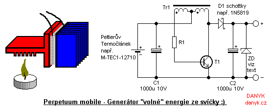
Introduction: This device is not a true perpetual motion machine or a source of free energy from the atmosphere; however, it presents an intriguing experiment, particularly for beginners and enthusiasts of alternative energy sources. It enables the generation of...

Generating sine waves with controlled frequencies over a wide range is challenging when using RC or LC sinusoidal oscillators. However, this can be effectively achieved using a wideband digital square wave oscillator, a counter, and a weighted summing network....
Integrated AF power amplifiers have experienced significant advancements in recent years, offering enhanced power and ease of use. The TDA1519C from Philips features two power amplifiers that provide 11 W per channel in stereo mode or 22 W in...
This circuit generates speed pulses from the speed-dependent voltage spikes produced by commonly used types of PC power supply fans, which are superimposed. The circuit utilizes the voltage spikes generated by the fan's operation to create a series of speed...