
free energy generator from a candle

The described device operates on the principles of thermoelectric generation, leveraging the Seebeck effect, which occurs in thermocouples. In this configuration, the thermoelectric cooler is repurposed to function in reverse, where a temperature gradient across its junctions induces an electromotive force (EMF). The use of a candle as a heat source is practical for small-scale applications, offering a simple yet effective means of generating thermal energy.
The choice of a large passive heatsink is critical for maintaining the necessary temperature differential between the hot and cold sides of the thermocouple. This heatsink should be made of a material with high thermal conductivity, such as aluminum or copper, to enhance heat dissipation. The efficiency of the thermoelectric generator can be improved by maximizing the temperature difference, thus optimizing the output voltage.
In terms of circuit design, the integration of a Joule thief inverter allows for the conversion of the low voltage generated by the thermocouple into a higher voltage suitable for powering small electronic devices. The inverter's operation is based on a self-oscillating circuit that boosts the voltage while consuming minimal power. The inclusion of a zener diode in the circuit aids in voltage regulation, providing a stable output for devices that require a specific voltage threshold.
Overall, this experimental device serves as an educational tool for understanding the fundamentals of thermoelectric generation and energy conversion, as well as providing insights into renewable energy applications. The modest power output may be suitable for low-power electronics, making it an interesting project for those exploring alternative energy solutions.Introduction: It is not any real perpetuum mobile, source of free energy from the atmosphere or anything like that, but it is, especially for beginners and enthusiasts of alternative energy sources, an unusual and very interesting experiment :). This device allows you to produce electricity from heat of burning candles or any other h eat source (burner, central heating, boiler, radiator. ). The conversion of thermal energy into electricity is utilized by Peltier cell (thermocouple). It is a reliable method without using any moving parts (unlike the thermal power plants). Although power is not high, it is sufficient for many small battery appliances. The principle of the device is simple: If one side of the thermocouple is warmed and the other cooled, thermocouple generates an electrical voltage. (The cooling is neeeded as the second law of thermodynamics says no machine can only work by being heated - simply told) Heating is provided by candle.
Cooling is provided by a large passive heatsink from old CPU. Cooling fan would probably not be possible because its consumption is likely to exceed the power of the generator. The greater the temperature difference, the greater the output voltage thermocouple can provide. I am usind a M-TEC1-12710 thermoelectric cooler (TEC), but can use other types. Here it operates in reverse mode. I built two prototypes, the first creates a voltage about 0. 8 V in stable state. Second prototype generates around 0. 9 - 1V and short circuit current to almost 0. 5 A. The voltage is too small to be used directly to power appliances, but it can be increased by the inverter.
To test the generator, the joule thief inverter with LED was used - it starts to operate from 0. 4 V. To power other appliances the circuit on schematic diagram below can be used. The output is suitable to connect a zener diode stabilizing the voltage at the desired value. The inverter can be used to power appliances requiring voltage in rande of 1. 5 - 6V. 🔗 External reference
Related Circuits
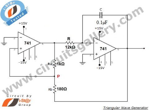
An operational amplifier-based triangular waveform generator is a simple circuit that is widely used in function generators. This circuit utilizes the 741 operational amplifier to create a triangular wave generator. The output waveform of an integrator will be triangular...
The first positive pulse from a classic 555-based oscillator is always 1.6 times longer than the subsequent pulses. This discrepancy arises because, during the initial cycle, capacitor C2 begins charging from 0 V. While this is typically not an...
The ratio R1/R2 determines the amplitude of the triangle wave in relation to the square-wave output. The frequency of oscillation for both waveforms can be calculated using the equation: fo = 1/(4R3C1) * (R2/R1). In this circuit, R1 and R2...
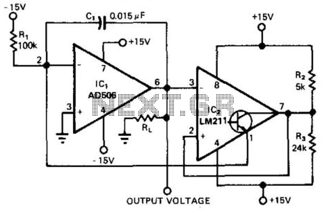
This circuit provides a 0-to-10-V output excursion from 0.4 Hz to 100 kHz, characterized by its simplicity and compact size. The negative current through Rl generates a positive slope for the ramp and causes the output of IC1 to...
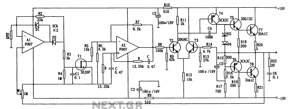
The low-frequency signal generating circuit demonstrates excellent performance characterized by stable operation, high output power, and minimal waveform distortion. It serves as an ideal source for low-frequency measurement signals. The circuit includes an operational amplifier (A) with a feedback...

This well-known circuit can be implemented using any rail-to-rail output comparator or the classic LMC555. The output period is defined by the equation 2log(2)RC = 1.386RC, exhibiting a stability of better than ±100 ppm/°C concerning temperature variations and ±100...