
FM Telephone Bug

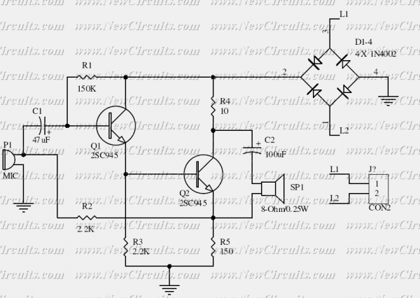
The FM Telephone Bug is designed to intercept and transmit audio signals from a telephone line. The circuit typically consists of a few key components: a microphone or audio pickup, an FM modulator, a power supply, and an antenna.
The audio signal is captured from the phone line and fed into the FM modulator, which converts the audio signal into an FM radio frequency signal. This modulation allows the audio to be transmitted over radio frequencies, which can then be received by any standard FM radio tuned to the appropriate frequency.
Power for the circuit can be derived from the telephone line itself or from an external battery source. It is crucial to ensure that the power supply used does not interfere with the normal operation of the telephone line. The antenna is typically a simple wire that is tuned to the frequency of transmission, allowing for effective broadcasting of the modulated signal.
The operational frequency can be adjusted based on the design of the FM modulator, which may include variable capacitors or inductors to fine-tune the output frequency. Proper shielding and grounding techniques should be employed to minimize interference and enhance signal clarity.
It is essential to note that the use of such devices may be subject to legal restrictions, as intercepting and transmitting telephone conversations without consent can violate privacy laws. Therefore, it is important to consider the legal implications of deploying an FM Telephone Bug in any application.FM Telephone Bug. Here is a simple transmitter that when connected to a phone line, will transmit anything on that line (execpt the dial tone) to any FM radio. The frequency. 🔗 External reference
Related Circuits
Many a times one needs an extra telephone ringer in an adjoining room to know if there is an incoming call. For example, if the telephone is installed in the drawing room you may need an extra ringer in...
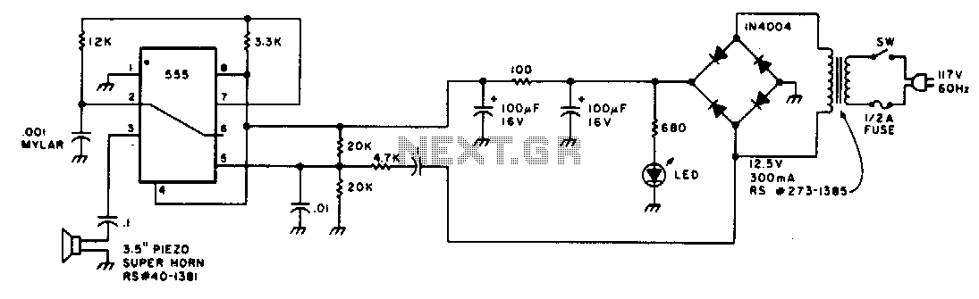
Low-intensity ultrasonic sound waves in the 30-45 kHz frequency band repel insects and small rodents. The unit is designed to generate a swept square wave from 30 to 45 kHz. The LM555 integrated circuit (IC) is configured as an...
This circuit diagram represents a simple yet effective transmitter circuit, capable of transmitting telephone conversations. When the telephone receiver is on the hook, the line voltage is approximately 48 volts. The R7 preset resistor is adjusted to achieve a...
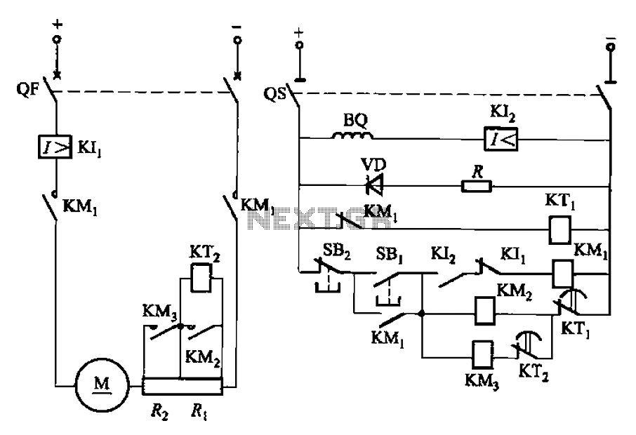
The circuit illustrated in Figure 3-191 features a DC motor armature circuit that includes two series startup resistors, Ri and Rz. The operation of the motor is controlled using buttons for starting and stopping. During the startup phase, two...
Typically, a single telephone is connected to a telephone line. If an additional telephone is needed at a distance, a parallel line is installed for connecting the second telephone. This straightforward parallel line arrangement presents issues such as loss...
This is the basis of electronics telephone sets. You can use it to replace the talking circuit of an old telephone set with new design, better noise rejection and reliability one. Also you can use it to build a...