
FM Telephone Bugs

The small telephone bug is a compact and efficient device designed to intercept audio signals from a telephone line and transmit them wirelessly to an FM receiver. This device operates independently using its own power source, eliminating the need for external power supplies. The simplicity of the design is reflected in its low component count, making it an accessible project for electronics enthusiasts.
The circuit typically consists of a few key components: a microphone to capture audio signals, an amplifier to boost the microphone's output, and an FM transmitter circuit to modulate the audio signals onto a radio frequency. The FM transmitter may utilize a simple oscillator circuit, often based on a transistor, to generate the necessary frequency for transmission.
The microphone is usually connected to the amplifier, which enhances the audio signal before it is fed into the FM modulator. The modulator converts the audio signal into an FM signal that can be picked up by standard FM receivers. The entire circuit is designed to operate with minimal power consumption, allowing for prolonged use without frequent battery replacements.
A schematic diagram of the circuit would typically illustrate the connections between these components, highlighting the power supply configuration, signal flow, and any necessary tuning elements to adjust the transmission frequency. This project provides an excellent opportunity to learn about analog audio processing and radio frequency transmission in a hands-on manner.Small telephone bug. Listen telephone line on your FM receiver. It is self powered. Small part count. Circuit diagram, schematics, electronics project.. 🔗 External reference
Related Circuits

A long time ago, when telephones were simple and reliable from an electrical standpoint, telecom operators installed surge protection on all telephone lines exposed to storm risks. Paradoxically, with the advent of delicate and expensive equipment such as electronic...
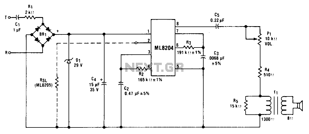
This circuit utilizes ML8204/ML8205 devices. The components illustrated result in an output frequency that oscillates between 512 Hz (fin) and 640 Hz (fb) at a modulation rate of 10 Hz (t). The circuit employing ML8204/ML8205 devices is designed for frequency...
The circuit automatically lights a bulb upon the arrival of a telephone ring and simultaneously mutes the audio from the music system or TV while the telephone handset is off-hook. The lighting of the bulb not only indicates an...
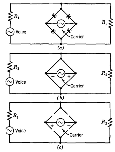
The Type C system was first installed around 1925 and has been extensively utilized since then. It incorporates the most desirable features of previously considered systems. Similar to the Type A system, the carrier signal is suppressed, minimizing the...
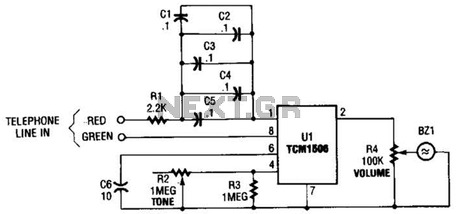
The circuit utilizes the TCM1506 ring detector/driver integrated circuit, which is a monolithic IC designed to replace mechanical bells in telephones. It is powered and activated by the telephone line's ringing signal, which ranges from 40 to 150 V...
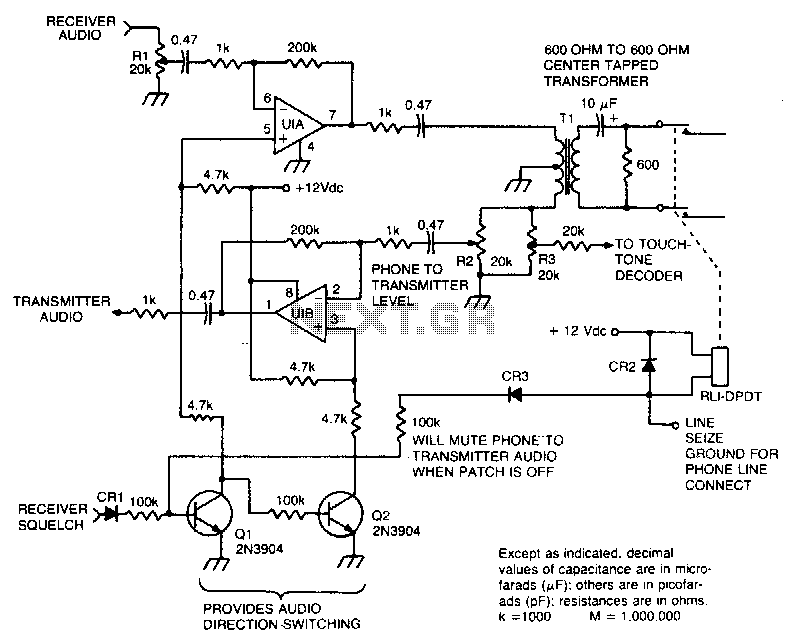
This circuit facilitates the communication link between the receiver and the phone line, as well as the phone line and the transmitter, utilizing an operational amplifier (op-amp) for signal amplification. The described circuit connects a receiver to a phone line...