
fm telephone circuits

The FM telephone circuit operates by utilizing the existing telephone line to power its components, which eliminates the need for an external power source. The circuit is designed to intercept the audio signals from both the microphone and speaker of the telephone. This is achieved through a series connection that allows the circuit to access the audio signals without disrupting the normal operation of the telephone.
The FM transmitter within the circuit modulates the audio signals onto a carrier wave within the specified frequency range of 90 to 95 MHz. This frequency range is chosen to align with standard FM radio frequencies, making the transmitted audio easily receivable by common FM radios. The circuit may include a simple oscillator, a modulator, and an antenna for effective transmission.
The compact design of the PC board is critical, as it must fit within the limited space of the telephone housing. Components such as resistors, capacitors, and integrated circuits are selected for their small size and low power consumption. The use of surface-mount technology (SMT) may be employed to further reduce the footprint of the circuit.
In practical applications, users can tune their FM radios to the designated frequency to listen to the conversation taking place on the telephone. This feature can be useful for various purposes, including monitoring calls or for hands-free operation. However, it is essential to consider legal regulations regarding the interception of telephone conversations in the applicable jurisdiction before using such a device.The FM telephone circuit is built on a PC board that is so small it can easily be fitted inside the housing of a telephone making it an instant pseudo-speak earphone. This FM circuit connects in series with telephone line, steals power from it, and transmit at both sides of the conversation to an FM radio tuned between 90 and 95 MHz.
🔗 External reference
Related Circuits
Make two telephones ring on stage. This involves sending a signal down a line to the phones. An old telephone exchange system was initially sought but not found. Several circuit ideas have been discovered, but the goal is to...
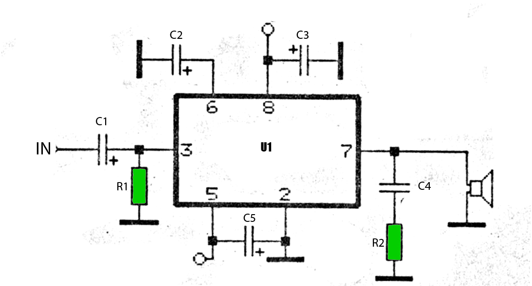
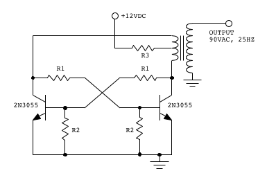
The car power amplifier utilizes the SI1050GL integrated circuit (IC) as the primary amplification component. It delivers an output power of 50 Watts at an 8-ohm mono impedance. The amplifier operates with a DC voltage of up to 25...
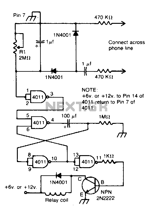
Connected across the bell circuit of a phone, this circuit activates a relay when the phone is ringing. It can utilize delay contacts to operate any bell, siren, buzzer, or lamp. The described circuit functions as a relay activation mechanism...
This self-build project can simulate a telephone call/connection between any two local telephone devices. This for a fraction of the outlay of some commercial units, many with cost-increasing features that usually are not required. The circuit is centred on...
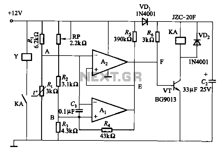
Electronic temperature control circuit for imported car air conditioners. It utilizes operational amplifiers A1 and A2, specifically the LM393 model. An adjustment potentiometer (RP) is included, allowing modification of the temperature range. The adjustment range includes a power temperature...
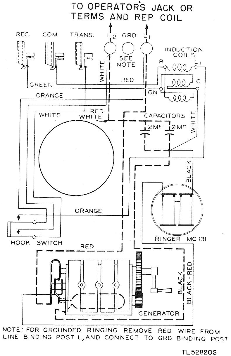
The EE-91 is a wall-mounted metal telephone box. It is a common battery phone, meaning the transmitter current is sourced from the central office battery. It features a single gong ringer and is equipped with a hand generator for...