
Telephone relay
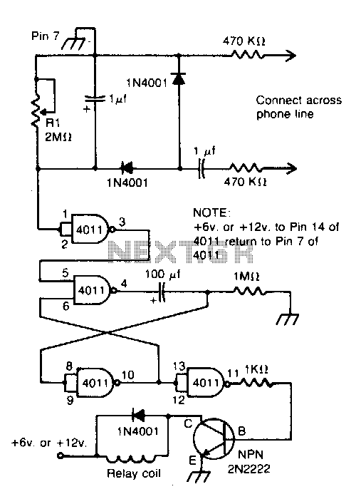
The described circuit functions as a relay activation mechanism that engages when a phone receives an incoming call. It is integrated across the bell circuit, which is the part of the phone responsible for ringing when a call is received. The primary component of this circuit is a relay, which serves as an electromechanical switch that can control a higher power device in response to a lower power signal.
When the phone rings, the bell circuit generates a voltage that is detected by the relay. This voltage energizes the relay coil, causing the relay contacts to close. The closing of the contacts can then be used to power various devices such as bells, sirens, buzzers, or lamps. The inclusion of delay contacts allows for the operation of these devices with a predetermined time delay, providing flexibility in the timing of the alert.
For schematic representation, the circuit typically includes a relay with a coil connected in parallel to the phone's bell circuit. The relay contacts can be configured as normally open (NO) or normally closed (NC), depending on the desired operation of the connected device. A diode may be added in parallel with the relay coil to prevent back EMF from damaging other circuit components when the relay is de-energized.
Overall, this circuit design is straightforward yet effective for enhancing alert systems associated with incoming phone calls, providing additional notification options beyond the standard ringing sound.Connected across the bell circuit of phone, this circuit closes a relay when the phone is ringing Use the delay contacts to actuate any bell, siren, buzzer or lamp. 🔗 External reference
Related Circuits
This schematic represents a simple water or liquid level sensor relay switch circuit, designed to control electronic appliances based on water levels. The circuit is particularly useful for automatically turning off a water pump when a water tank, pool,...
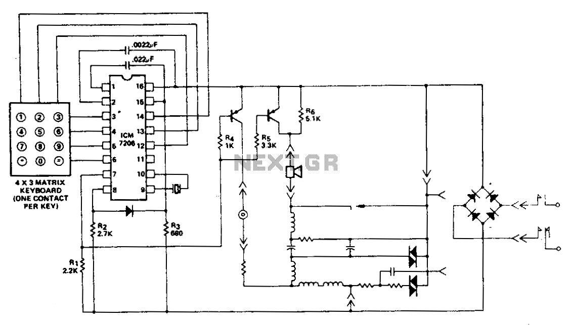
This encoder utilizes a single contact per key keyboard and manages all other switching functions electronically. A diode connected between terminals 8 and 15 limits the output to no more than 1 V negative concerning the negative supply, Vss....
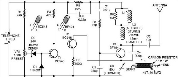
This schematic outlines a simple FM transmitter designed to operate using a phone line for both power and audio signal reception. By connecting the device to the desired phone line, it enables monitoring of conversations. Users can tune their...
This 555 timer circuit toggles a relay when a button is pressed. Pins 2 and 6, the threshold and trigger inputs, are held at half the supply voltage by two 10K resistors. When the output is high, the capacitor...
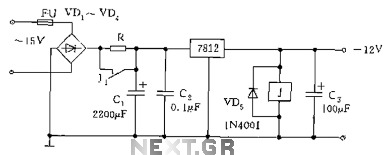
The figure below illustrates the use of a relay in the starting circuit. The power input connects through a resistor R, which serves two purposes: first, it prevents a large current from the capacitor C1 from affecting the power...

This circuit was designed for use in a hi-fi showroom, where a choice of speakers could be connected to a stereo amplifier for comparative purposes. The circuit serves as a speaker selector that facilitates the connection of multiple speakers to...