
FM Transmitter

The described transmitter circuit is centered around a Hartley oscillator configuration, which is known for its simplicity and effectiveness in generating radio frequency signals. The oscillator consists of a tank circuit formed by the inductor (the coil) and the capacitor. In this specific design, the capacitor is connected to the base of the transistor, but due to the characteristics of VHF operation, the base-emitter capacitance of the transistor effectively shorts out the capacitor at these frequencies, allowing the circuit to function correctly.
The inductor, composed of four turns of 18 SWG (standard wire gauge) wire, is wound around a quarter-inch diameter former. This choice of wire gauge and former size is critical for achieving the desired inductance value and ensuring that the coil can handle the RF currents without significant losses. The coil's design also influences the transmitter's frequency stability and output power.
The aerial tap, positioned about one and a half turns from the supply end of the coil, is an important aspect of the circuit. This tap allows for the extraction of the RF signal, which can then be transmitted through an antenna. The precise location of the tap is crucial, as it affects the impedance and matching of the antenna system, which in turn influences the overall efficiency of the transmitter.
Furthermore, the transmitter exhibits excellent audio sensitivity, particularly when utilizing an ECM (Electret Condenser Microphone) type microphone insert. This type of microphone is favored in many applications due to its high sensitivity and low noise characteristics. The combination of the Hartley oscillator's design and the ECM microphone allows for clear audio transmission, making this transmitter suitable for various applications, including amateur radio and wireless audio transmission systems.
Overall, this circuit design exemplifies a practical approach to RF transmission, balancing simplicity with effective performance, making it a valuable tool for electronics enthusiasts and professionals alike.This small transmitter uses a hartley type oscillator. Normally the capacitor in the tank circuit would connect at the base of the transistor, but at VHF the base emitter capacitance of the transistor acts as a short circuit, so in effect, it still is. The coil is four turns of 18swg wire wound around a quarter inch former. The aerial tap is about one and a half turns from the supply end. Audio sensitivity is very good when used with an ECM type microphone insert. 🔗 External reference
Related Circuits
This transmitter needs heatsink at 2N2219. With the C4 we regulate the frequency. With their C7, C8 we adapt the resistance of aerial (practically to them we regulate so that it is heard our voice in the radio as...
The wireless FM transmitter circuit described here includes an additional RF power amplifier stage following the oscillator stage, which increases the power output to 200-250 mW. The wireless FM transmitter circuit functions by modulating audio signals onto a radio frequency...
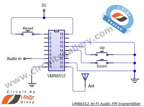
This article provides the circuit schematics for an FM transmitter along with the necessary explanations. The primary component utilized is the VMR6512 IC, a highly integrated FM audio signal transmitter chip designed for Hi-Fi audio applications. This chip can...
This is the basic FM transmitter that I built. In theory, according to electronics, it shouldn't work but works fine and is very sensitive. It can transmit the signal up to 45 yards (about 40 meters). A sensitive FM...
This is an AM transmitter schematic diagram. The circuit is divided into two halves: an audio amplifier and an RF oscillator. The oscillator is constructed around Q1 and its associated components. The tank circuit, consisting of L1 and VC1,...
The circuit of an AM transmitter is designed to transmit amplitude modulated (AM) double sideband (DSB) signals. A modulated AM signal consists of a carrier and two symmetrically spaced sidebands. The two sidebands have the same amplitude and carry...