
AM Transmitter

The AM transmitter circuit is designed to modulate audio signals onto a carrier wave for transmission. The audio amplifier section processes the input audio signal, enhancing its amplitude to a level suitable for modulation. Typically, this section may include operational amplifiers or transistor-based amplifiers to achieve the desired gain.
The RF oscillator generates the carrier frequency, which is crucial for AM transmission. It operates using Q1, which is likely a transistor or a field-effect transistor (FET), along with passive components such as resistors and capacitors. The oscillator's frequency is determined by the tank circuit formed by inductor L1 and variable capacitor VC1. The tunable nature of VC1 allows the user to adjust the frequency, enabling operation across a range from 500 kHz to 1600 kHz, which is suitable for AM broadcasting.
In this schematic, the output of the RF oscillator can be connected to an antenna for transmission. The design must consider impedance matching to ensure efficient power transfer to the antenna. Additionally, filtering components may be included to suppress harmonics and ensure that the transmitted signal meets regulatory standards for spectral purity.
Overall, this AM transmitter schematic diagram illustrates a fundamental approach to building a basic AM transmitter, suitable for educational purposes or hobbyist projects. Proper attention to component selection, layout, and tuning will enhance the performance and reliability of the transmitter.This is AM transmitter schematic diagram. The circuit is in two halfs, an audio amplifier and an RF oscillator. The oscillator is built around Q1 and associated components. The tank circuit L1 and VC1 is tunable from about 500kHz to 1600KHz.. 🔗 External reference
Related Circuits
The Circuit shown can transmit voice to exceptionally good range. Tune trimmer to hear the signal to your near radio. Frequency range is 88-108 MHz. Max current consumption is 30mA. You can power the bug with a 9Volt Battery,...
Antenna is the means by which a wireless operator puts his signal into the space and also through which he picks up the signals of the stations with which he wants to communicate. Hence after having a good Receiver...
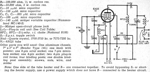
Although this CW transmitter circuit was published in 1955 in Popular Electronics, it remains legal for today's amateur radio operators. Portions of the 40-meter and 80-meter bands are still reserved exclusively for CW operation. As of 2011, the frequencies...

This is a mini FM transmitter powered by two transistors and designed by Tony van Roon. This compact transmitter is straightforward to assemble, and its signals can be received on any standard FM radio. It has a range of...

This compact FM transmitter operates with an RF output power of 500mW and can be powered by a 12-15V battery or power supply. The signal is modulated using frequency modulation (FM) techniques and employs four transistors. The transmitter consists...
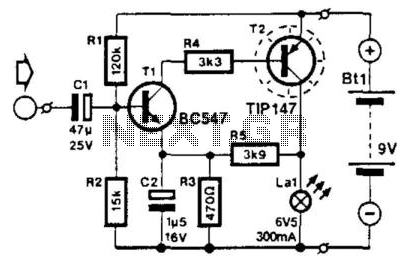
This circuit modulates the current through a lamp filament. It is designed for use with a low-voltage lamp featuring a thin, straight filament, which responds quickly to variations in filament voltage. Direct current (DC) is applied to bias the...