
Simplest Piezo Driver Circuit Explained

The circuit for driving a piezoelectric transducer typically involves several key components: a low-power signal source, a transistor, an inductor, and the piezo transducer itself. The signal source can be a microcontroller or any other low-frequency oscillator capable of generating a suitable signal. The transistor acts as a switch or an amplifier, allowing the low power signal to control a larger current flowing through the inductor.
The inductor plays a pivotal role in this circuit by storing energy when current flows through it. When the transistor is activated, the current builds up in the inductor, which then releases this energy to the piezo transducer, generating a mechanical vibration. This process effectively translates the electrical signal into a mechanical output, which is the fundamental operation of a piezoelectric device.
The choice of transistor is important, as it must be capable of handling the required current and voltage levels without overheating. Common transistor types used in this application include bipolar junction transistors (BJTs) or field-effect transistors (FETs), depending on the specific circuit requirements.
Additionally, the inductor value should be selected based on the frequency of operation and the desired resonance characteristics of the piezo transducer. A higher inductance will allow for more energy storage, enhancing the output to the transducer but may also affect the response time of the circuit.
In summary, the circuit for driving a piezoelectric transducer is a straightforward yet effective design that utilizes a transistor and an inductor to amplify a low-power signal, ultimately enabling the transducer to convert electrical energy into mechanical vibrations efficiently. Proper selection of components and circuit parameters is essential for optimal performance in various applications, including sound generation, sensing, and actuation.In the previous post we discussed a piezo transducer element and learned how to use it with electronic circuits. In this article we will see how a piezo tranducer can be driven or operated using a simple circuit. However the amplification procedure is not by using conventional amplifying circuits as used in systems incorporating speakers, but rath
er it is simply implemented through an inexpensive inductor. The low power frequency which may be available from a relevant circuit or an IC is first amplified using a transistor, and further more the transistor output is pumped up using an inductor. The use of a inductor becomes the most crucial stage for driving a piezo electric transducer. 🔗 External reference
Related Circuits
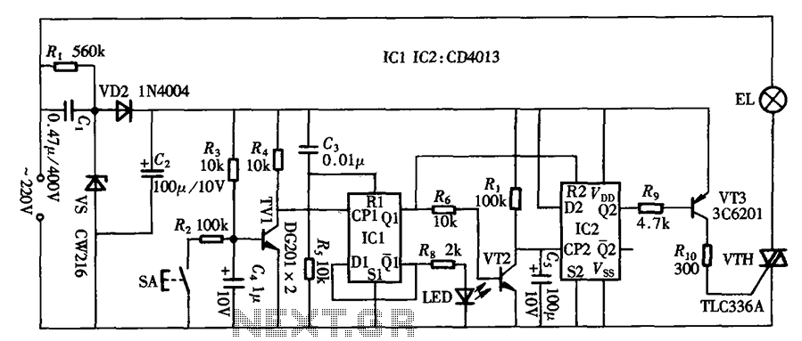
The circuit primarily utilizes a touch-delay switch composed of a pair of D flip-flops (CD4013). It can be employed in power switch applications for various machines. The delay switch can also function as a lighting control and features a...
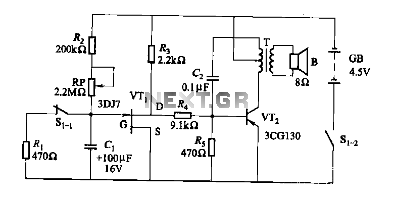
The darkroom circuit is designed for one-time exposure and emits an audible signal when the developing time is reached. This circuit can be utilized for photofinishing large timers and other applications. It comprises components such as FET VTi, resistors,...
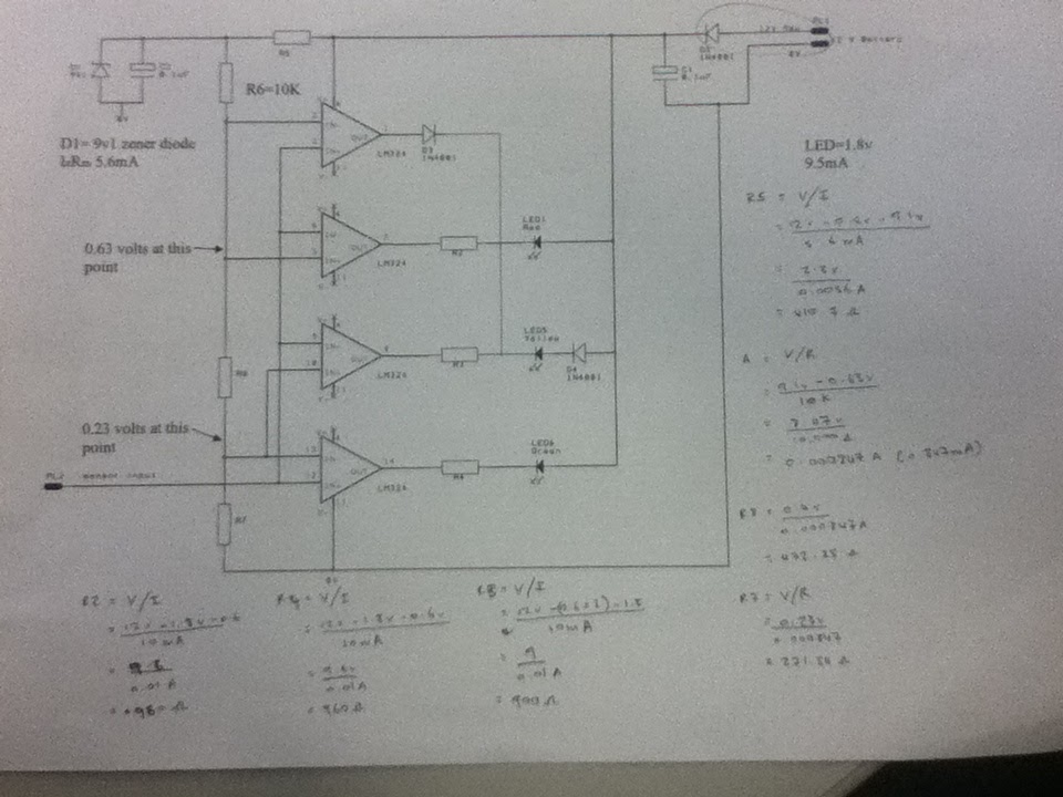
The diagram illustrates the connections for the inputs and outputs of each operational amplifier from the power source, detailing how each operational amplifier is configured to operate individual light-emitting diodes (LEDs). It also includes calculations for determining each resistor...

This stereo amplifier utilizes the NE5517/A and features an excellent tracking accuracy of 0.3 dB, which is typical. The offset can be adjusted using the potentiometer, Rp. For AC-coupled amplifiers, the potentiometer can be substituted with two 5.1 k...
A real-time controller is a device designed to continuously manage household devices, both in real-time and according to a predetermined schedule. This article focuses on a series of real-time controllers utilizing the AT89C2051 microcontroller, which serves this purpose effectively....
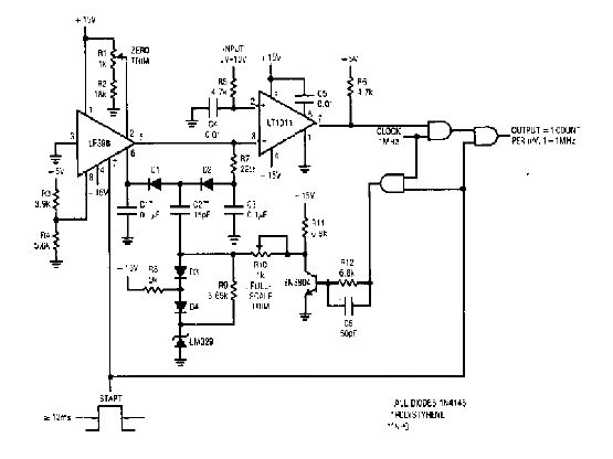
The simple 4-digit converter circuit has an output count of 1, designed to operate within a frequency range of f-IMHz to 10.000. All diodes used in the circuit are IN4146, and the capacitors are made of `POLYSTYRENE` NPO. The...