
Forklift battery circuit

The battery forklift operates on a well-defined electrical and mechanical structure that ensures efficient handling and maneuverability. The series connection of batteries provides a stable 30V DC output, which is essential for powering the motors and hydraulic systems. Motor M1, a two-speed series motor, is designed to deliver torque and speed control through a gear mechanism, facilitating the lifting and lowering of loads. The gear wheel drive system enables the forklift to navigate through tight spaces and perform precise movements.
Motor M2 plays a critical role in the hydraulic system, powering a high-pressure oil pump that enables the lifting mechanism of the forklift. This motor must operate reliably under varying load conditions to maintain the efficiency of the hydraulic system. The integration of the electric lock switch (S1) ensures that the forklift cannot be operated unless it is safe to do so, preventing accidental activation.
The direction switch (S2) allows the operator to select forward or backward movement, enhancing operational flexibility. The foot switch (SO1) serves as a safety feature, ensuring that the forklift can only be activated when the operator is ready and in control. The speed controller pedal (S02) provides a means to modulate the speed of the forklift, allowing for smooth acceleration and deceleration.
In summary, the design of the battery forklift incorporates essential components such as motors, switches, and control circuitry to create a robust and user-friendly handling tool for various industrial applications. Proper understanding and management of these components are vital for maintaining operational efficiency and safety in the workplace. Battery forklifts are railway stations, docks, warehouses balloon-like plant in two commonly used as a stacking and handling tools. Pictured It forklift battery shape and elect rical control circuitry, circle 2-18b It is composed of batteries in series battery electric forklift electric control path. GB is a concatenation of the 30V DC battery power supply. Motor Ml is driving the motor, series motor is a two-speed, through a gear wheel drive mechanism, drive things forward or backward with the shovel.
Granville string electric motor M2 is the motor for drag high international oil pump, high pressure oil input to the hydraulic system to operate the fork lift. Sl electric lock switch, S2 is a direction switch, soi for the foot switch. s02 speed controller pedal. The forklift and the governor will start the electric lock switch sl closed HL power indicator light, said power had access circuit, make ready supply.
The direction of the switch S2 handle into the desired direction, namely forklift forward or backward position. Release the parking brake handle stern, release the foot brake and the car, so that the foot switch is closed soi reset, and then gently depress the pedal speed controller SQ2 to dynamic contact with the stationary contact 0 contact, so that the entire mace switch S3 closed sets.
Related Circuits
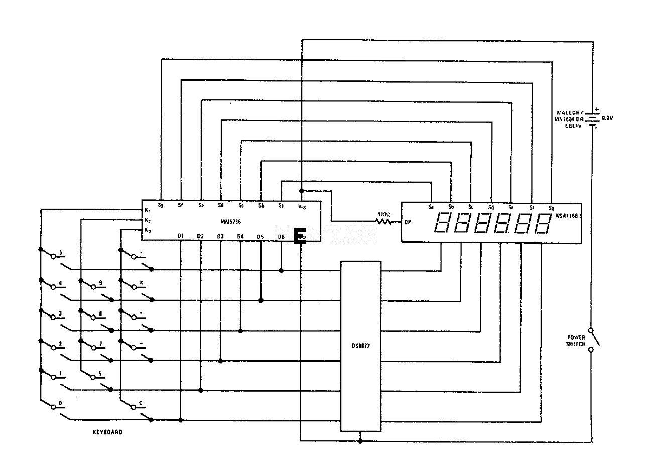
Configure the National Semiconductor DS8877 drive circuit as shown. When used with a 6-digit calculator and digital current conjunction, the current range is from 5 to 50 mA. The drive does not require standby power, and the operating voltage...
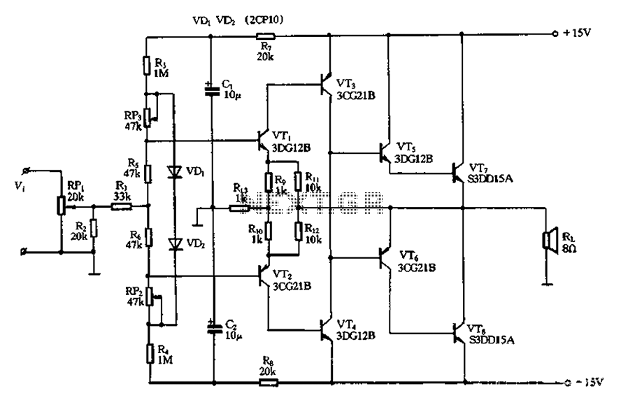
The circuit utilizes diode VDi, f Pooh to stabilize the base bias of transistors VTi and VT2, ensuring a more stable quiescent point when the supply voltage is within a specific range. In the event of temperature fluctuations, the...
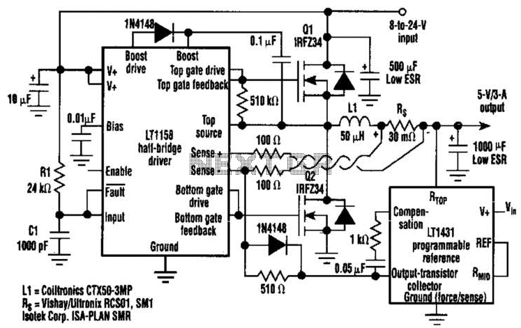
This regulator achieves 90% efficiency with a 12-V input and a 5-V output. It utilizes the LT1158 and LT1431 components from Linear Technology, Inc. High efficiency is accomplished by synchronously switching two power MOSFETs in a step-down switching regulator....
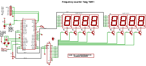
C code for a frequency counter circuit operating up to approximately 50 MHz, utilizing a multiplexed seven-segment display and employing Timer 1 to count the edges of the input signal. The frequency counter circuit described operates effectively within the range...
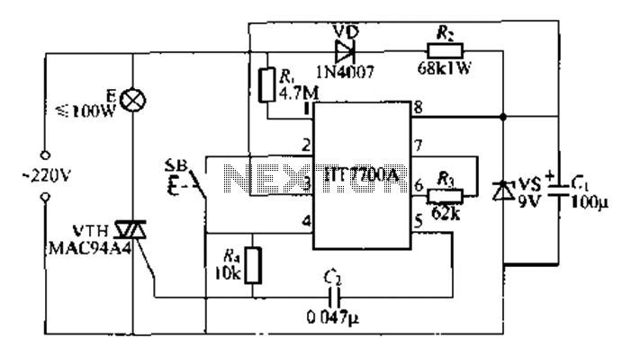
The HT7700A ASIC is designed for stepless dimming of lights, utilizing a single button control mechanism. It offers 96 levels of brightness adjustment. The HT7700A is fabricated using a CMOS process and comes in a standard D1P-S-pin package. The...
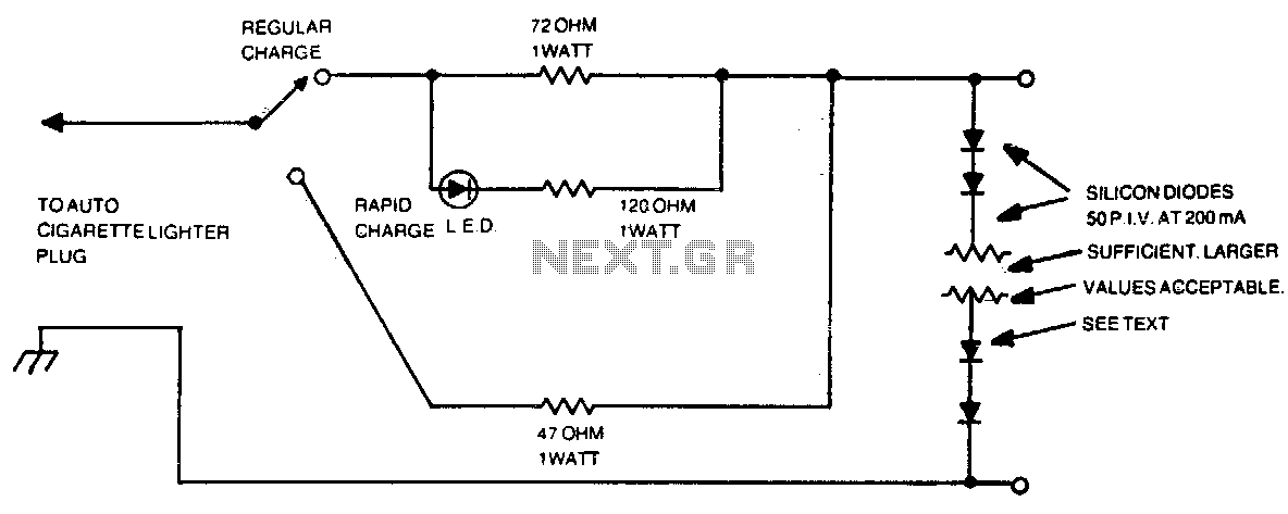
The number of silicon diodes across the output is determined by the voltage of the battery pack. Each diode is considered at 0 volts. For example, a 10-volt pack would require 10/0 = 157, or 16 diodes. In the context...