
Morse Practice Oscillator Circuit

The circuit utilizes a 555 timer IC, which is a versatile and widely used component in timing applications. In the astable mode, the 555 timer continuously oscillates between its high and low states, producing a square wave output. This square wave can be fed into a speaker or a piezo buzzer to generate audible tones.
The frequency of the generated audio note is determined by the resistor and capacitor values connected to the 555 timer. Specifically, two resistors (R1 and R2) and a capacitor (C1) are used to set the timing intervals. The frequency (f) of oscillation can be calculated using the formula:
f = 1.44 / ((R1 + 2 * R2) * C1)
By adjusting the values of R1, R2, and C1, the frequency of the output signal can be modified, allowing for a range of audio notes to be produced. For instance, increasing the capacitance of C1 will lower the frequency, resulting in a deeper tone, while decreasing it will raise the frequency, producing a higher pitch.
Additionally, the output of the 555 timer can be connected to a low-pass filter or an amplifier circuit to enhance the audio quality or adjust the volume. This flexibility makes the astable multivibrator configuration of the 555 timer suitable for various audio applications, including alarms, sound effects, and musical notes in electronic devices. A 555 timer configured as an astable multivibrator is used in this circuit lo generate an audio note. CI can be changed to vary the audio note as desired.
Related Circuits

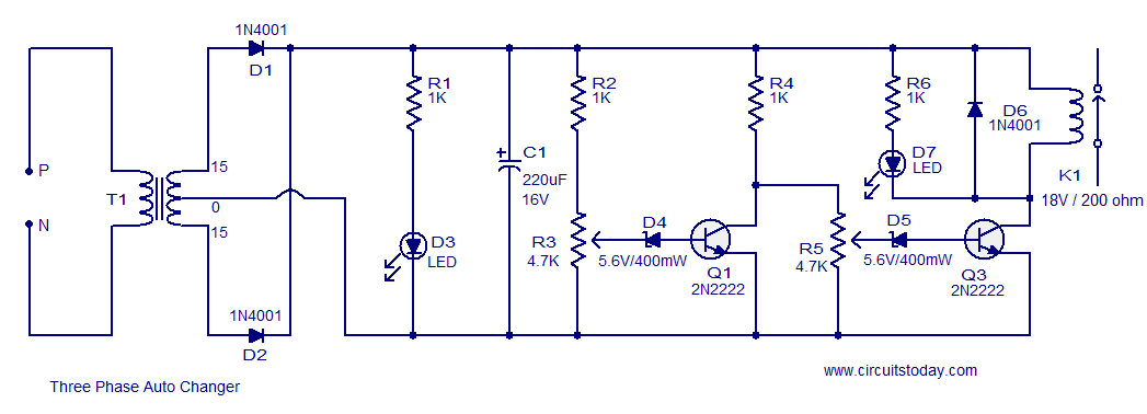
The figure illustrates that the DC Solid State Relay (SSR) in the input stage functions as an opto-isolator. When the switch output is high, the driver circuit inverts this signal to low. This process involves a light-emitting diode (LED)...
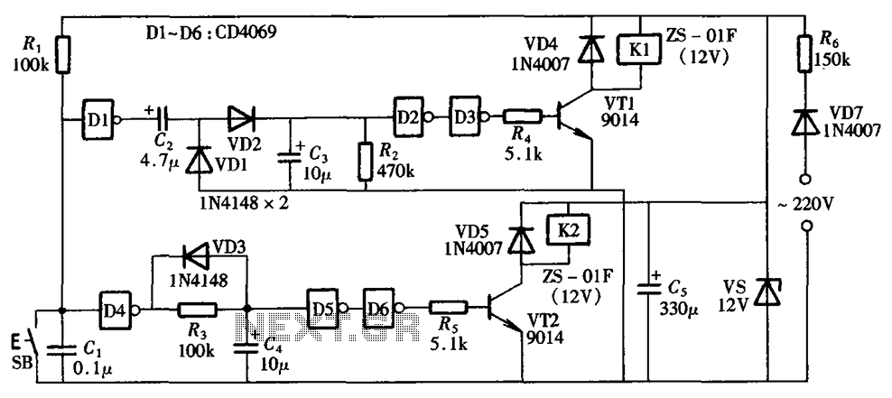
A one-button control switch is designed to control two relays, each of which can switch the load power on and off as needed. The circuit primarily consists of a hex inverter CD4049 and two self-locking DC relays. The circuit utilizes...
This circuit is a modification of a high and low voltage cut-off with delay and alarm circuit that was featured in Circuits Today. It has been tested and found to be reliable. The circuit can be adapted with minor...
The Mark3 version of the Infrared extender is specifically designed to control appliances that utilize high-frequency modulated infrared remote signals. The Mark3 Infrared extender functions as a bridge between a standard infrared remote control and appliances that operate with high-frequency...

The FM front-end circuit, also referred to as an FM receiver circuit, is composed of discrete components. This configuration presents challenges in debugging and is prone to difficulties in miniaturization, leading to its gradual replacement by FM radio integrated...

On a mountain bike, a common issue with traditional flashing LED lights from stores is the frequent problem of flat batteries and lights detaching. As an electronics student, a better solution was sought. A front wheel with a built-in...